
Sable V6-3.0L DOHC VIN S (2002)
Brake Rotor/Disc: Testing and Inspection
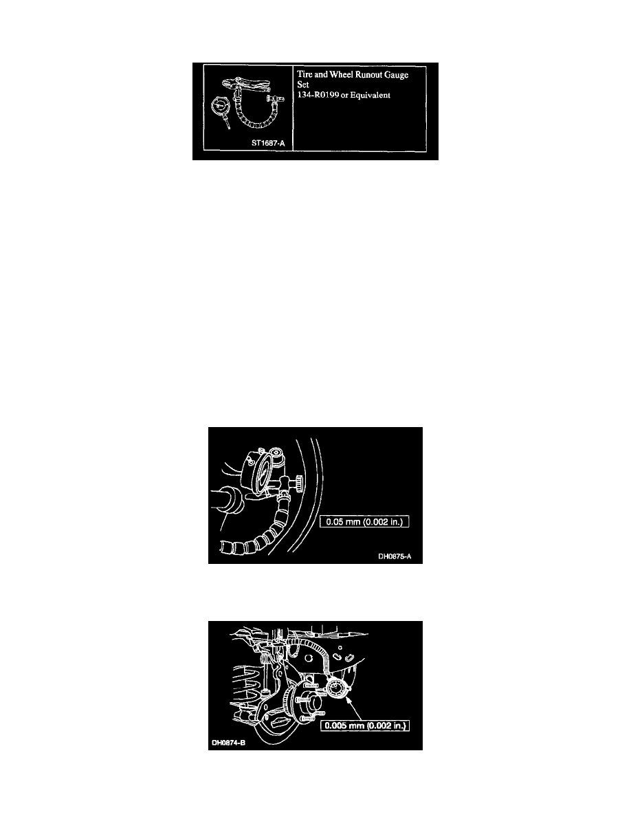
Runout Check
Special Tool(s)
CAUTION: The brake disc runout specification must be met to ensure correct brake performance without roughness complaints.
CAUTION: Do not install brake discs that are less than the minimum thickness specified. Do not machine a brake disc below the minimum thickness
specification.
NOTE: When installing brake discs, always align the painted match marks on the brake disc with those on the front hub.
NOTE: When installing brake discs, always apply high Temperature Nickel Anti-Seize Lubricant F6AZ-9L494-AA or equivalent meeting Ford
specification ESE-M12A4-A to the brake disc-to-front hub mating surfaces.
1. Do not remove the tire and wheel assembly. Tighten the wheel nuts to specification.
2. Raise and support the vehicle.
3. Assemble the special tool, using the spherical tip extension.
4. Locate an opening on the inboard side of the dust shield that will allow the dial indicator tip to be positioned at least 5 mm (0.2 inch) from the
outer edge of the brake disc.
5. NOTE: Do not clamp the gauge set to a vehicle component separated from the brake disc by a flexible joint, such as a ball joint or body mount.
Clamp the special tool on the vehicle, making sure the flexible indicator arm and probe tip do not touch the dust shield or tire while rotating.
6. Rotate the wheel for six revolutions, and record the total indicated runout.
7. If the total indicated runout exceeds the maximum specification, remove the brake disc.
8. Clean the brake disc mounting face of dirt, rust and foreign material.
9. Measure and record the total indicated runout of the hub face outside the stud circle.
10. Install a new front hub if the total indicated runout exceeds the maximum specification.