
Sable V6-3.0L DOHC VIN S (2002)
Hydraulic Cooling Fan Solenoid Valve: Description and Operation
PCM Outputs
Visctronic Drive Fan (VDF)
Visctronic Drive Fan (VDF)
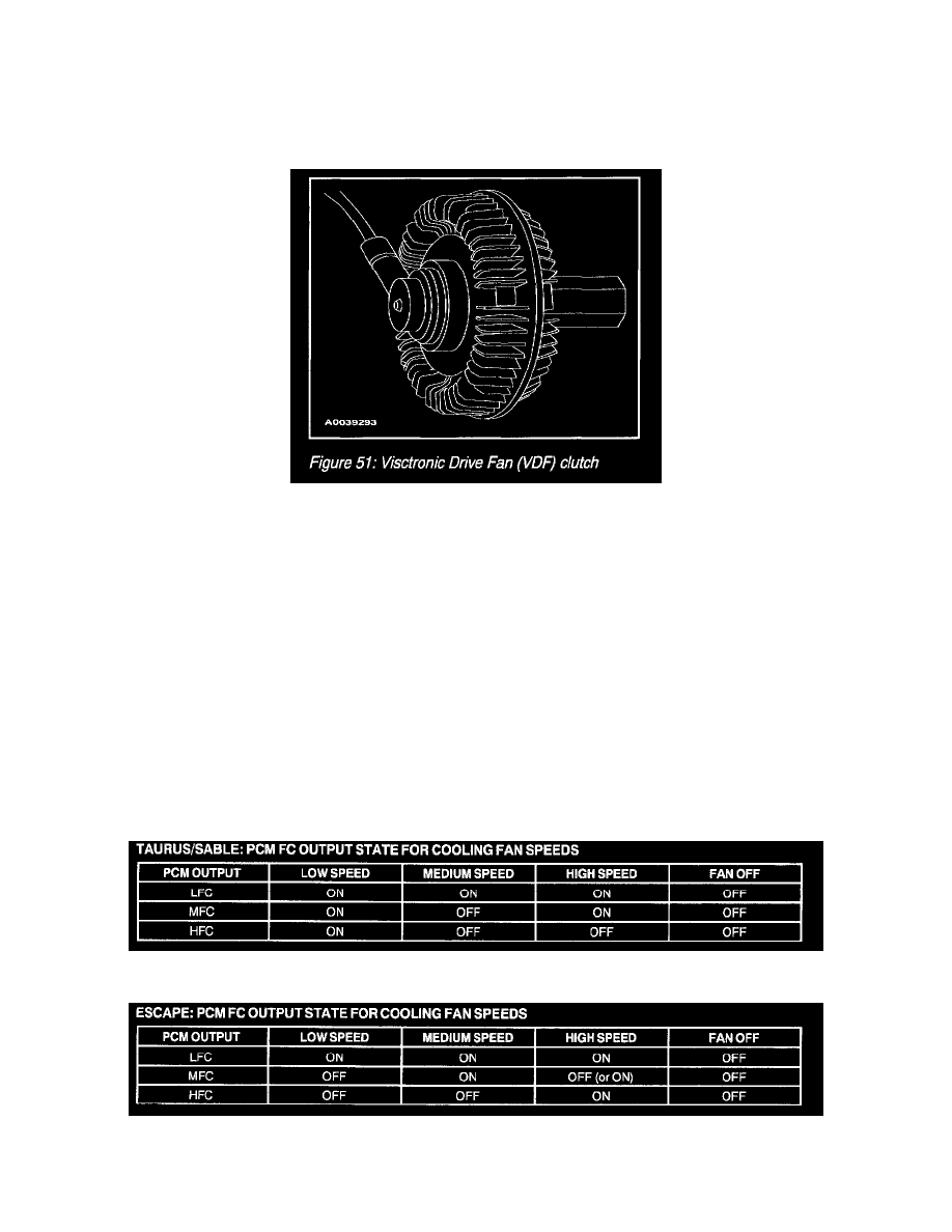
Visctronic Drive Fan (VDF) Clutch
The primary purpose for the Visctronic Drive Fan (VDF) clutch is to optimize fan energy (i.e. improved fuel economy) while meeting cooling
performance requirements. Successful optimization will also minimize objectionable fan noise. The operation is similar to the existing viscous fan
clutch, except viscous fluid flow is controlled by a Pulse Width Modulated (PWM) solenoid versus a bi-metal temperature sensor on the front of the
clutch.
The VDF consists of three main elements, a working chamber, a reservoir chamber, and a Fan Speed Sensor (FANSS). A fluid port valve controls
fluid flow from the reservoir into the working chamber. Once viscous fluid is in the working chamber, "shearing" of the fan clutch fluid will result in
fan rotation. The valve is activated via a pulse width modulated (PWM) output signal from the PCM. By opening and closing the fluid port valve, the
PCM can control approximate fan speed. Fan speed is monitored via a Hall-Effect sensor and is read by the PCM for closed loop operation.
The PCM will optimize the VDF fan speed based upon CHT, TFT, or AT cooling requirements. When either of these inputs is demanding increased
fan speed for vehicle cooling, the PCM will monitor the Hall Effect Fan Speed Sensor (FANSS), and output the resultant PWM signal to the fluid port
valve thus controlling to the required fan speed.
Fan Control
Fan Control
TAURUS/SABLE: PCM FC Output State For Cooling Fan Speeds Chart
ESCAPE: PCM FC Output State For Cooling Fan Speeds Chart
The PCM monitors certain parameters (such as engine coolant temperature, vehicle speed, A/C on/off status, A/C pressure, etc) to determine engine