
Sable V6-3.0L VIN 2 Flex Fuel (2005)
EGR Control Module: Description and Operation
EGR SYSTEM MODULE (ESM)
Overview
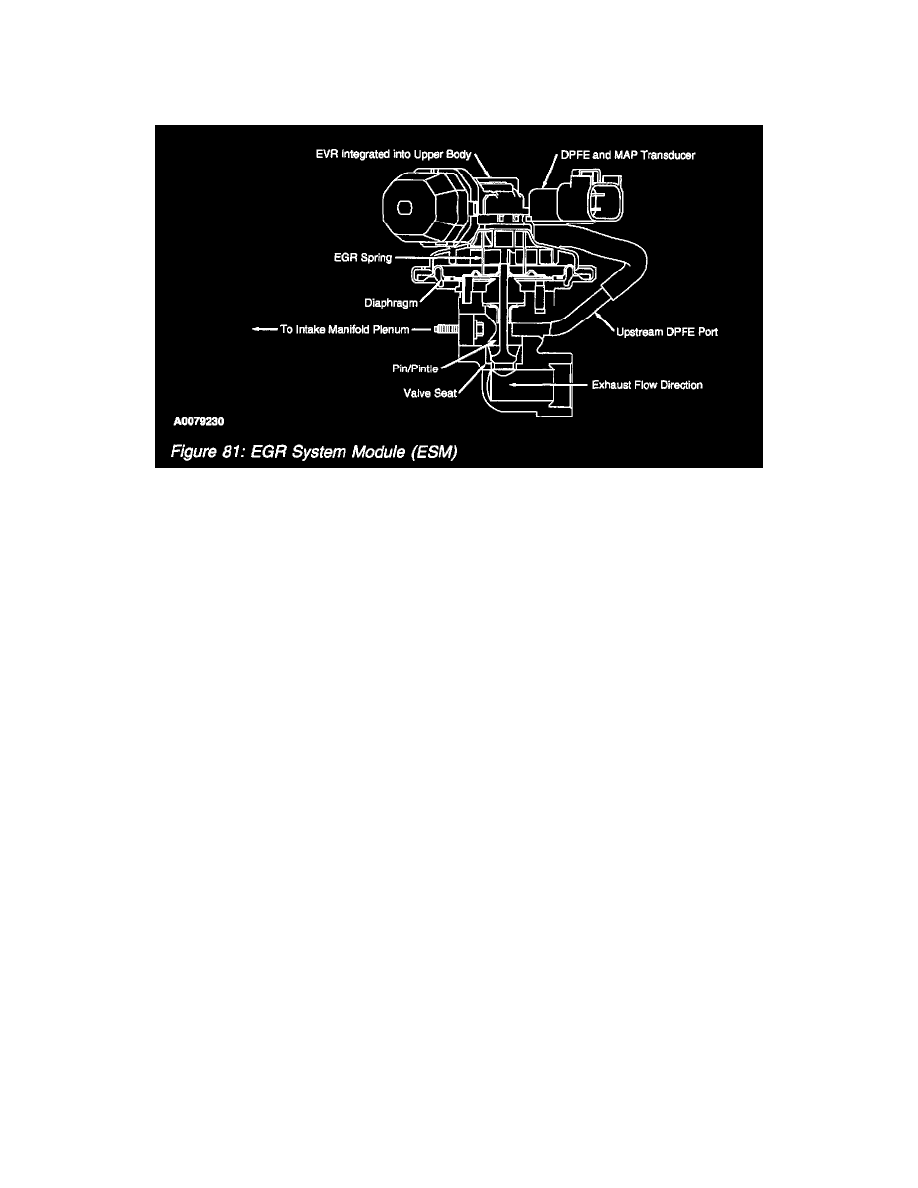
EGR System Module (ESM)
The ESM is an updated DPFE EGR system. It functions in the same manner as the conventional DPFE system, however the various system
components have been integrated into a single component called the ESM. The flange of the valve portion of the ESM bolts directly to the intake
manifold with a metal gasket that forms the measuring orifice. This arrangement increases system reliability, response time, and system precision. By
relocating the EGR orifice from the exhaust to the intake side of the EGR valve, the downstream pressure signal measures manifold absolute pressure
(MAP). The system provides the PCM with a differential DPFE signal, identical to a traditional DPFE system.
The delta pressure feedback EGR monitor is comprised of a series of electrical tests and functional tests that monitor various aspects of the EGR
system operation.
First, the DPFE sensor input circuit is checked for out of range values (P1400/P0405 P1401/P0406). The EVR output circuit is checked for opens and
shorts (P1409/P0403).
NOTE: EGR normally has large amounts of water vapor that are the result of the engine combustion process. During cold ambient temperatures,
under some circumstances, water vapor can freeze in the DPFE sensor, hoses, as well as other components in the EGR system. In order to prevent MIL
illumination for temporary freezing, the following logic is used.
If an EGR system malfunction is detected below 0°C (32°F), only the EGR system is disabled for the current driving cycle. A DTC is not stored and
the I/M readiness status for the EGR monitor will not change. The EGR monitor will, however, continue to operate. If the EGR monitor determines
that the malfunction is no longer present, the EGR system will be enabled and normal system operation will be restored.
If an EGR system malfunction is detected above 0°C (32°F), the EGR system and the EGR monitor is disabled for the current driving cycle. A DTC is
stored and the MIL is illuminated if the malfunction has been detected on 2 consecutive driving cycles.
After the vehicle has warmed up and normal EGR rates are being commanded by the PCM, the low flow check is carried out. Since the EGR system is
a closed loop system, the EGR system will deliver the requested EGR flow as long as it has the capability to do so. If the EVR duty cycle is very high
(greater than 80% duty cycle), the differential pressure indicated by the DPFE sensor is evaluated to determine the amount of EGR system restriction.
If the differential pressure is below a calibrated threshold, a low flow malfunction is indicated (P0401/P0406).
Finally, the differential pressure indicated by the DPFE sensor is also checked at idle with zero requested EGR flow to carry out the high flow check.
If the differential pressure exceeds a calibrated limit, it indicates a stuck open EGR valve or debris temporarily lodged under the EGR valve seat
(P0402).
If the inferred ambient temperature is less than 0°C (32°F), or greater than 60°C (140°F), or the altitude is greater than 8,000 feet (BARO less than
22.5 in-Hg), the EGR monitor cannot be run reliably. In these conditions, a timer starts to accumulate the time in these conditions. If the vehicle
leaves these extreme conditions, the timer starts to decrement, and, if conditions permit, will attempt to complete the EGR flow monitor. If the timer
reaches 800 seconds, the EGR monitor is disabled for the remainder of the current driving cycle and the EGR Monitor I/M Readiness bit will be set to
a ready condition after one such driving cycle. Vehicles will require 2 such driving cycles for the EGR monitor to be set to a ready condition.