
Sable V6-3.0L VIN 2 Flex Fuel (2005)
17. Position the driver air bag module to the steering wheel.
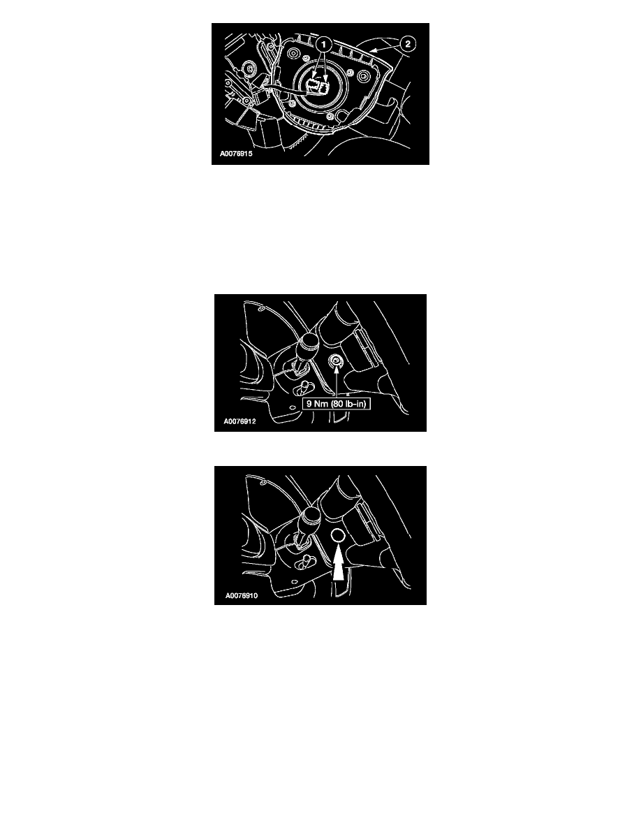
1
CAUTION: The clockspring electrical connectors are unique and cannot be reversed when connected to the driver air bag module.
Match the electrical connector key to the keyway in the drive air bag module. Do not force the electrical connectors into the driver air
bag module.
Connect the driver air bag module electrical connectors as noted during removal.
2
Position the driver air bag module to the steering wheel.
18. Install the two driver air bag module bolts (one shown).
19. Install the two steering wheel back cover nuts (one shown).
20. WARNING: The restraint system diagnostic tool is for restraint system service only. Remove from vehicle prior to road use. Failure to
remove could result in injury and possible violation of vehicle safety standards.
Make sure all restraint system diagnostic tool(s) that may have been installed during the repair have been removed from the vehicle and all SRS
components are connected.
21. Turn the ignition switch from OFF to ON.
22. Install the RCM fuse F2.20 (10A) to the SJB and install the cover.
23. WARNING: Be sure that nobody is in the vehicle and that there is nothing blocking or set in front of any air bag module when the
battery ground cable is connected.
Connect the battery ground cable.