
Sable V6-3.0L VIN U (1999)
Electronic Brake Control Module: Service and Repair
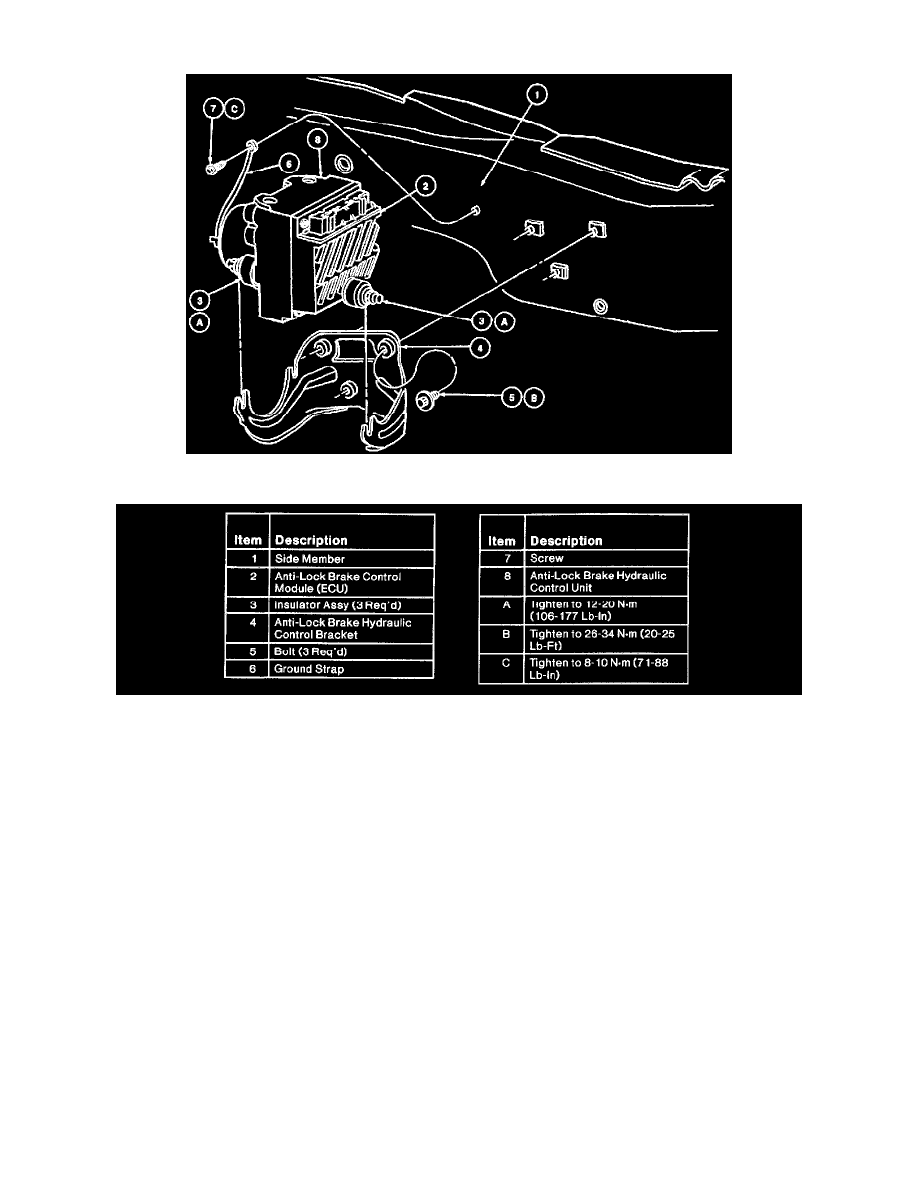
Fig. 115 ABS Module & Hydraulic Control Unit Assembly (Part 1 Of 2)
Removal
1. Disconnect and remove battery from vehicle.
2. Remove battery tray and mounting bracket from vehicle.
3. Disconnect anti-lock brake wiring connector from anti-lock brake control module.
4. Remove two tubes from inlet ports and four tubes from outlet ports of anti-lock brake hydraulic control unit. Plug each port to prevent brake fluid
from spilling onto paint and wiring.
5. Remove screw and anti-lock pump motor ground strap.
6. Remove three nuts retaining anti-lock brake control module assembly to anti-lock brake hydraulic control bracket and remove assembly from
vehicle.
7. Remove three anti-lock brake hydraulic control bracket mounting bolts and anti-look brake hydraulic control bracket.
8. NOTE: Use caution removing control module from hydraulic control unit to avoid damage to the internal connector.
Remove five screws from anti-lock brake control module.
9. Remove anti-lock brake control module from anti-lock brake hydraulic control unit.
Installation
1. Position anti-lock brake control module onto anti-lock brake hydraulic control unit.
2. Install five screws.
3. Install anti-lock brake control module.
4. Position anti-lock brake hydraulic control bracket. Install three mounting bolts. Tighten to 26 - 34 Nm (20 - 25 ft. lbs.).
5. Position anti-lock brake control module assembly into anti-lock brake hydraulic control bracket. Install three retaining nuts and tighten to 16 - 24
Nm (12 - 17 ft. lbs.). Install anti-lock pump motor ground strap to frame rail. Tighten screw to 8 - 10 Nm (71 - 88 inch lbs.).
6. Connect four tubes to outlet ports on side of anti-lock brake hydraulic control unit and two tubes to inlet ports of anti-lock brake hydraulic control
unit and tighten tube nuts to 14 - 24 Nm (11 - 17 ft. lbs.).