
Sable V6-3.0L VIN U (1999)
Brake Pedal Assy: Service and Repair
Removal
1. Disconnect battery ground cable.
2. Remove pushpins and remove instrument panel close-out panel.
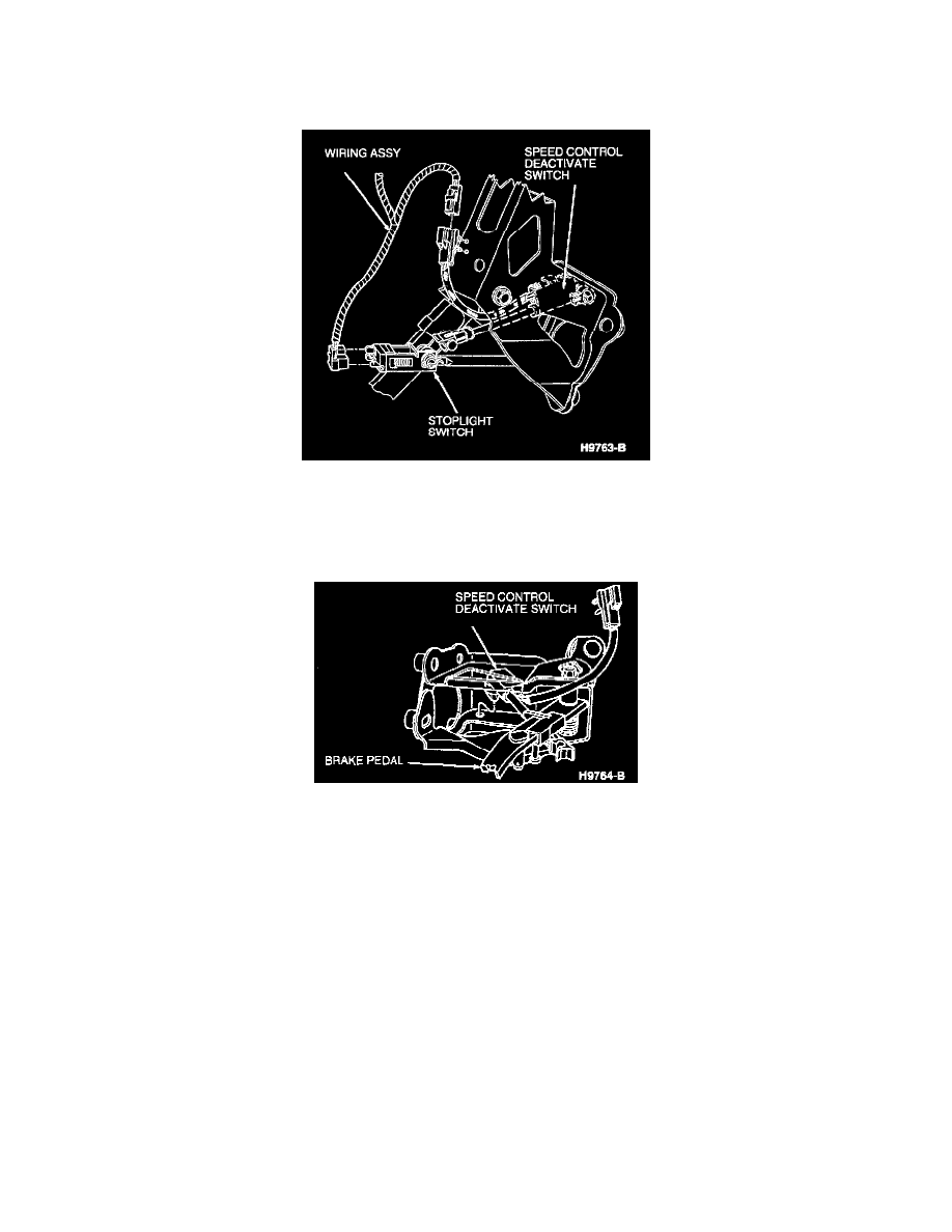
3. Disconnect connector from stoplight switch. Disconnect wiring harness from speed control deactivate switch.
4. Remove yellow push rod retainer and white nylon washer. Slide stoplight switch along brake pedal pin just far enough for hole of switch frame to
clear pin. Remove black brake master cylinder push rod bushing from brake pedal pin.
5. Remove four brake booster retaining nuts at brake pedal support. Slide booster push rod off brake pedal pin.
6. Remove two bolts retaining brake pedal to upper cowl panel reinforcement and remove brake pedal.
7. Disconnect speed control deactivate switch from brake pedal and bracket. Disconnect connector from pedal bracket and remove speed control
deactivate switch.
8. Remove speed control deactivate switch adapter from brake pedal arm and stud.
Installation
1. Clean and apply light coat of clean engine oil meeting Ford specification WSS-M2C910-A1 to the white nylon washers and to black brake master
cylinder push rod bushing.
2. Install white speed control deactivator switch adapter onto pedal pin and swing it onto pedal arm until it can rotate no further. Make sure the
adapter hook is behind pedal arm.
3. Install speed control deactivate switch into hole in brake pedal bracket and onto post on switch adapter. Install switch connector to brake pedal
bracket.
4. Install brake pedal over power brake booster studs. Install two bolts retaining brake pedal to upper cowl panel reinforcement. Tighten bolts to 21 -
29 Nm (16 - 21 ft. lbs.).
5. Install booster push rod onto brake pedal pin. Install four nuts on power brake booster studs. Tighten brake booster retaining nuts to 21 - 29 Nm
(16 - 21 ft. lbs.).
6. Install black brake master cylinder push rod bushing onto pedal pin and into push rod. The head of the bushing should be on side of push rod away
from pedal arm.
7. Position stoplight switch so it straddles push rod with slot frame on pedal pin, hole frame just clearing pin and switch actuating plate along flat on
the push rod. Slide stoplight switch onto pin and push rod. The flat on push rod should be contacting stoplight switch actuating plate. Slide switch
and push rod toward pedal arm causing the pin to go through switch frame hole. Install white washer and yellow push rod retainer. Make sure
retainer is locked securely across entire pedal pin.
8. Connect wiring harness connector to stoplight switch. Connect wiring harness connector to speed control deactivate switch.