
Sable V6-3.0L VIN U (1999)
Brake Pad: Service and Repair
Front
Removal
1. Remove brake master cylinder filler cap. Check fluid level in brake master cylinder reservoir. Remove brake fluid until brake master cylinder
reservoir is half full. Discard removed fluid.
2. Raise vehicle on hoist.
3. Remove wheel and tire assembly from front disc brake rotor mounting face. Use care to avoid damage or interference with disc brake caliper, front
disc brake rotor shield or front wheel knuckle.
4. Remove rear brake pin retainers.
5. NOTE: It is not necessary to disconnect hydraulic connections.
Lift disc brake caliper from front disc brake caliper anchor plate and front disc brake rotor. Do not pry directly against metal caliper piston or
damage will occur.
6. NOTE: To prevent damage, do not allow disc brake caliper to hang by the front brake hose.
Position disc brake caliper out of the way.
7. Remove inner outer brake shoe and lining assembly from front disc brake caliper anchor plate.
8. Inspect both rotor braking surfaces. Minor scoring or buildup of lining material does not require machining or replacement of front disc brake
rotor.
INSTALLATION
NOTE: If front disc brake rotor has been moved relative to the wheel hub and rust or dirt may have shifted between front disc brake rotor and wheel
hub, on-vehicle rotor runout can be increased significantly. This can lead to brake shudder. Clean all dirt or foreign material from mating surfaces of
caliper locating pins and caliper housing ears. Dirt can cause caliper locating pins to be crooked after rear brake pin retainers are torqued, preventing
disc brake caliper from sliding properly.
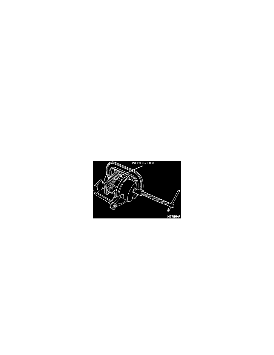
Retracting Caliper
1. CAUTION: Metal or sharp objects cannot come into direct contact with piston surface or damage will result.
Use a 10 cm (4 inch) C-clamp and a wood block or other flat stock, like an old brake shoe and lining to seat hydraulic caliper piston in its bore.
This must be done to provide clearance for disc brake caliper to fit over front disc brake rotor during installation. Extra care must be taken during
this procedure to prevent damage to metal caliper piston.
2. Remove all rust buildup from inside of disc brake caliper (shoe contact area).
3. Install inner and outer brake shoe and lining assembly with clip-on insulators into front disc brake caliper anchor plate.
4. Install disc brake caliper.
5. Install rear brake pin retainer. Tighten to 31 - 38 Nm (23 - 28 ft. lbs.).
6. CAUTION: Failure to tighten lug nuts in a star pattern may result in high rotor runout, which will speed up the development of brake
roughness, shudder and vibration.
Install wheel and tire assembly on vehicle. Tighten lug nuts to 115 - 142 Nm (85 - 104 ft. lbs.) using Rotunda Accutorq Lug Nut Socket
164-R0303 or equivalent on a 1/2 inch air impact wrench, or use a torque wrench.
7. Lower vehicle.
8. Pump brake pedal prior to moving vehicle to position brake linings. Refill brake master cylinder with Ford High Performance DOT 3 Motor
Vehicle Brake Fluid C6AZ-19542-AB or DOT 3 equivalent meeting Ford specification ESA-M6C25-A. If DOT 3 is not available use DOT 4
Brake Fluid meeting Ford specification SAE-J-1704-DOT4.
9. Road test vehicle.