
Sable V6-3.0L VIN U (1999)
Part 2 Of 2
7. Remove brake shoe retracting springs from lower brake shoe and lining attachments and upper shoe-to-adjusting lever attachment points. This will
separate rear brake shoes and linings and disengage adjuster mechanism.
8. Remove horseshoe parking brake lever pin retainer and spring washer. Remove from trailing shoe.
Installation
1. Apply a light coating of Silicone Brake Caliper Grease and Dielectric Compound D7AZ-19A331-A or equivalent meeting Ford specification
ESE-M1C171-A to rear brake backing plate-brake shoe, contact areas.
2. Apply a light coat of Silicone Brake Caliper Grease and Dielectric Compound D7AZ-19A331-A or equivalent meeting Ford specification
ESE-M1C171-A to threaded areas of brake adjuster screw and brake shoe adjusting screw socket. Assemble brake adjuster with stainless steel
washer. Turn brake shoe adjusting screw socket all the way down on screw, then back off one turn.
3. Install parking brake lever to trailing shoe with spring washer and new parking brake lever pin retainer. Crimp parking brake lever pin retainer to
securely retain parking brake lever.
4. Position trailing shoe on rear brake backing plate. Install brake shoe hold-down spring pin and brake shoe hold-down spring. Attach rear parking
brake cable.
5. Position leading shoe on rear brake backing plate. Install brake shoe hold-down spring pin and brake shoe hold-down spring and attach lower
brake shoe adjusting screw spring to brake shoes.
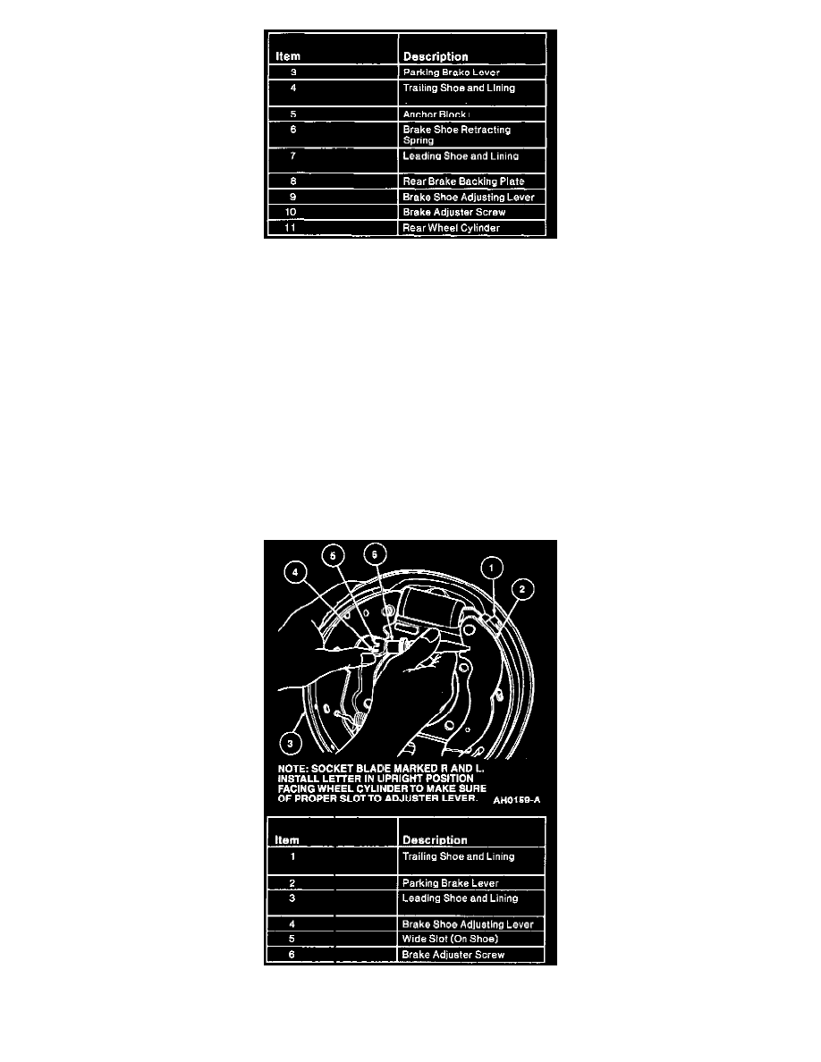
6. Install adjuster assembly to slots in rear brake shoes and linings. Socket end must fit into slot in leading shoe (wider slot). Slot in adjuster nut must
fit into slots in trailing shoe and parking brake lever.