
Sable V6-3.0L VIN U (1999)
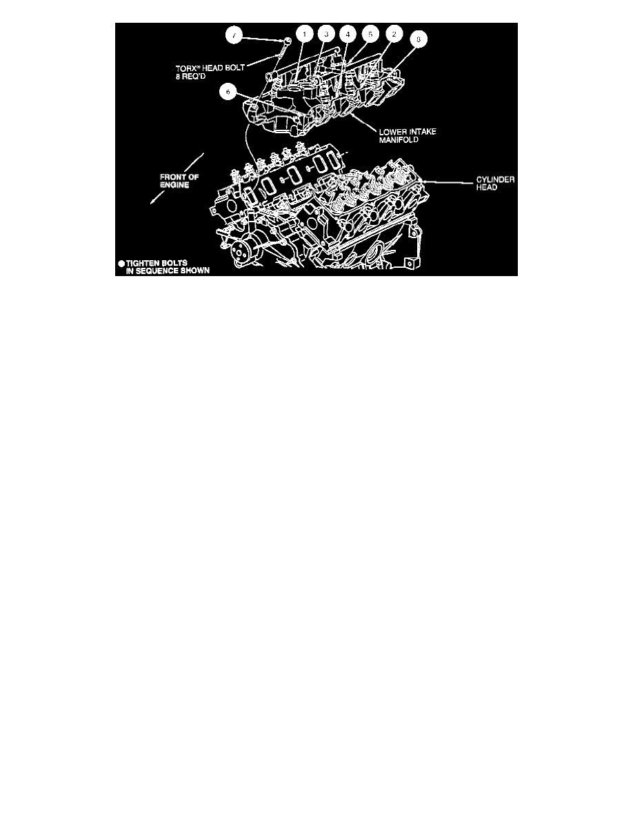
9. Carefully lower intake manifold into position aligning intake manifold bolt holes to those in cylinder head. Use care to prevent distributing silicone
sealer which can cause sealing voids.
-
Install bolts No. 1, 2, 3, and 4 and hand-tighten.
-
Install remaining bolts and tighten in sequence shown in two steps:
-
Tighten in numerical sequence to 20-30 Nm (15-22 ft. lbs.)
-
Then tighten again in sequence to 26-32 Nm (20-23 ft. lbs.)
10. NOTE: Rocker arm seats must be fully seated into cylinder head and push rod must be fully seated in rocker arm and valve tappet sockets prior to
final tightening.
Lubricate removed push rods and rocker arms with Engine Assembly Lubricant D9AZ-19579-D or equivalent meeting Ford specification
ESR-M99C80-A. Move rocker arms into position with push rods and snug rocker arm seat retaining bolt. Rotate crankshaft to position camshaft
lobes straight down and away from valve tappet.
-
Tighten retaining bolt for rocker arm seats into cylinder head to 7-15 Nm (6-11 ft. lbs.)
-
Final tighten rocker arm seat retaining bolt to 26-38 Nm (20-28 ft. lbs.) in any position.
11. Install valve covers.
12. Install engine control sensor wiring to each fuel injector. Secure wire harness retainers to valve cover stud bolts.
13. Install ignition coil to rear of LH cylinder head. Tighten retaining bolts to 40-55 Nm (30-40 ft. lbs.)
14. Install ignition wire harness retainers to valve cover stud bolts and connect ignition wires to spark plugs and ignition coil.
15. Install upper intake manifold.
16. Install EGR valve to exhaust manifold tube from intake manifold to EGR valve.
17. Install fuel tubes.
18. Install fuel tube safety retaining clips.
19. Install upper radiator hose and heater water hoses. Tighten retaining clamps securely.
20. Connect vacuum lines to premarked locations.
21. Connect electrical connections to idle air control valve, engine coolant temperature sensor, throttle position sensor, EGR backpressure transducer,
EGR vacuum regulator solenoid, ignition coil and water temperature indicator sender unit.
22. NOTE: Engine coolant is corrosive to all engine bearing material. Replacing oil after removal of a coolant carrying component prevents damage.
Fill and bleed engine cooling system.
23. Fill crankcase to the proper level with Motorcraft Super Premium 5W30 Motor Oil XO-5W30-QSP or equivalent meeting Ford specification
WSS-M2C153-G.
24. Install air cleaner outlet tube to throttle body an engine air cleaner.
25. Install crankcase ventilation tube to valve cover and air cleaner outlet tube. Install aspirator hose to air cleaner outlet tube.
26. Connect battery ground cable.
27. Start engine and check for coolant, oil, fuel and vacuum leaks.