
Sable V6-3.0L VIN U (1999)
Piston: Service and Repair
Removal and Installation
Removal
1. Drain engine cooling system.
2. Remove upper intake manifold.
3. Remove lower intake manifold.
4. Remove cylinder heads.
5. Remove oil pan.
6. Remove oil pump and oil pump intermediate shaft.
7. Before removing the piston, inspect the top of each cylinder bore. If a ridge has formed at the top of the cylinder it must be removed before the
piston is removed. Remove ridge as follows:
a. Turn crankshaft until the piston to be removed is at the bottom of cylinder bore.
b. Place a clean shop cloth over the piston head to collect cuttings.
c. Remove ridge using Cylinder Ridge Reamer T64L-6011-EA or equivalent. Never cut into the ring travel area more than 0.794 mm (1/32 inch)
when removing the ridge.
8. Turn crankshaft until the piston to be removed is at the lowest point of its travel. If more than one piston is being removed, identify the pistons and
connecting rod caps. Each component should be installed in its original position during assembly.
9. NOTE: The cylinder number is stamped on the top of the piston. Matched letters are stamped on the sides of corresponding connecting rod and
cap.
Remove connecting rod cap retaining nuts and cap.
10. CAUTION: Use care to prevent damage to bearing surfaces or possible engine damage may occur.
Install a 50 mm (2 inch) piece of 3/8-inch fuel hose (or similar protector) over connecting rod cap studs and push piston out through top of the
cylinder bore.
11. Install connecting rod cap and hold in position with cap retaining nuts.
12. If piston is to be disassembled, refer to Pistons, Piston Pins and Rings Disassembly.
13. Inspect cylinder bore. If new piston rings are to be installed on the piston, a visible cross-hatch pattern should be obvious on cylinder bore wall.
14. If honing is required, remove glaze from cylinder wall using spring-loaded hone. Follow manufacturer's instructions when using this type of
equipment. After honing, thoroughly clean cylinder bore using a detergent and water solution.
Installation
1. Lightly oil all bolt and stud bolt threads with Motorcraft Super Premium 5W30 Motor Oil XO-5W30-QSP or equivalent meeting Ford
specification WSS-M2C153-G before installation except those specifying special sealant.
Lubricate cylinder wall and piston with Engine Assembly Lubricant D9AZ-19579-D or equivalent meeting For specification ESR-M99C80-A.
2. Install a 50 mm (2 inch) piece of 3/8 inch fuel hose (or similar protector) on the connecting rod studs.
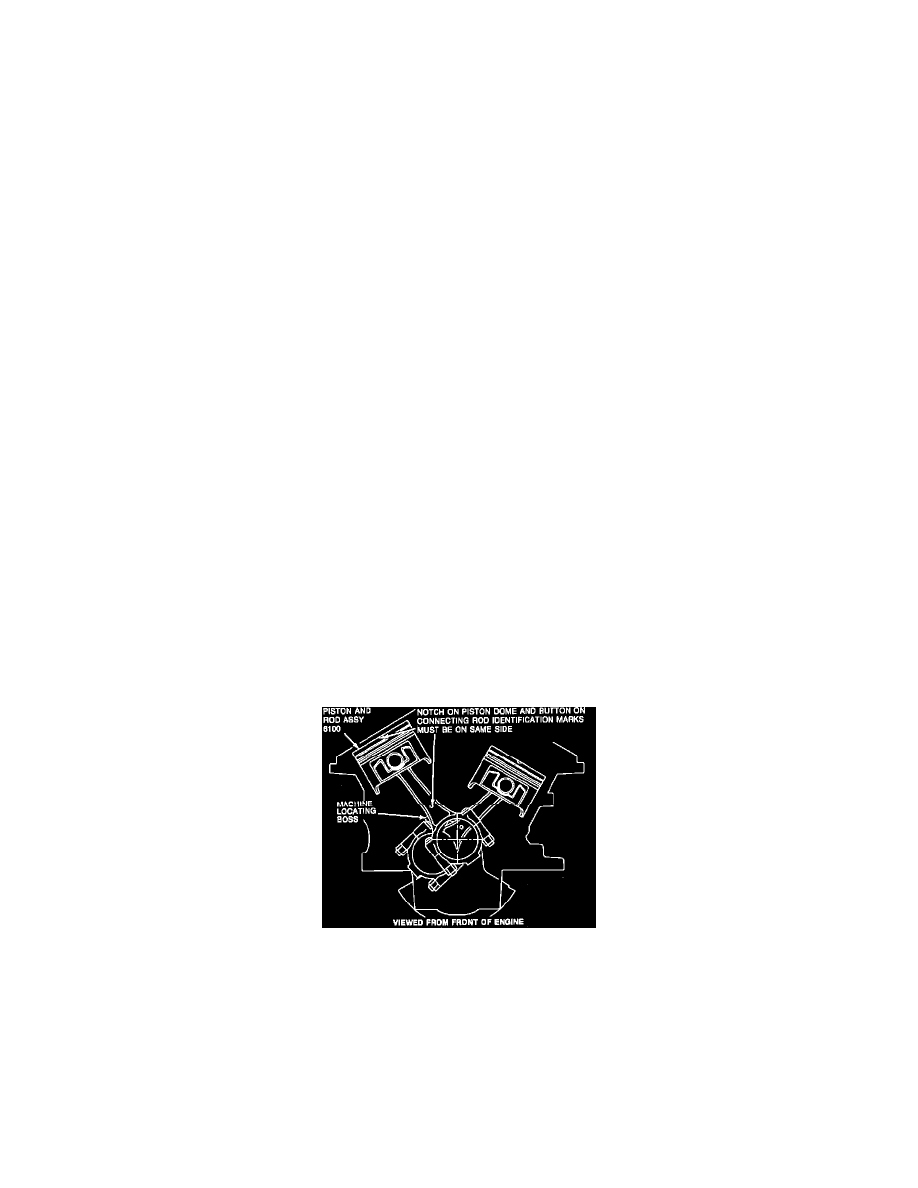
Piston & Rod Assembly
4
3. CAUTION: As piston is tapped into bore with a wooden hammer handle, guide connecting rod onto crankshaft journal to avoid damage
to bearing surfaces.
NOTE: Connecting rod and cap are not identified to cylinder position.
NOTE: Install the pistons in the same cylinders from which they were removed or to which they were fitted. The connecting rod and caps are
identified with matching correlation letters. Letters on the connecting rod and cap must be on the same side when installed in the cylinder bore. If a
connecting rod is transposed from one cylinder block or cylinder to another, new connecting rod bearings should be fitted.
Install piston using Rotunda Piston Ring Compressor 014-00290 or equivalent.