
Sable V6-3.0L VIN U (1999)
Multiplex Communication Network: Description and Operation
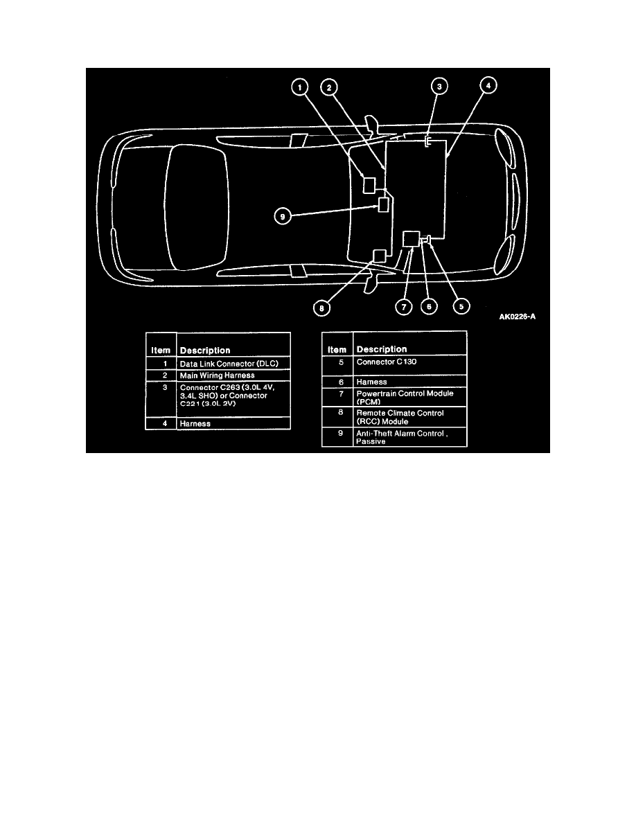
Multiplex Communication Network
System Components
The multiplex communication network provides:
-
the ability for module-to-module communication by sharing required inputs and outputs instead of each component having an input or output
wired directly to or from each affected module.
-
a common link for communication to an off-board tester through the Data Link Connector (DLC) located under the instrument panel to the right of
the steering column.
Three micro-processor based subsystems are included on this network:
-
powertrain control
-
passive anti-theft
-
climate control
The communication bus between these subsystems and the Data Link Connector (DLC) consists of an unshielded twisted pair of wires:
-
circuit 914 (T/O) Bus+
-
circuit 915 (PK/LB) Bus-
FAULT TOLERANCE
The multiplex communication network will remain operational in the event:
-
one circuit is severed.
-
one circuit is shorted to ground.
-
one circuit is shorted to battery positive voltage (B+).
-
a termination resistor is lost within a module.
-
one or more modules fail internally.
Any of these conditions will be detected and reported to the off-board tester during diagnostics in the form of a Diagnostic Trouble Code (DTC).
PURPOSE