
Sable V6-3.0L VIN U (1999)
Power Door Lock Switch: Testing and Inspection
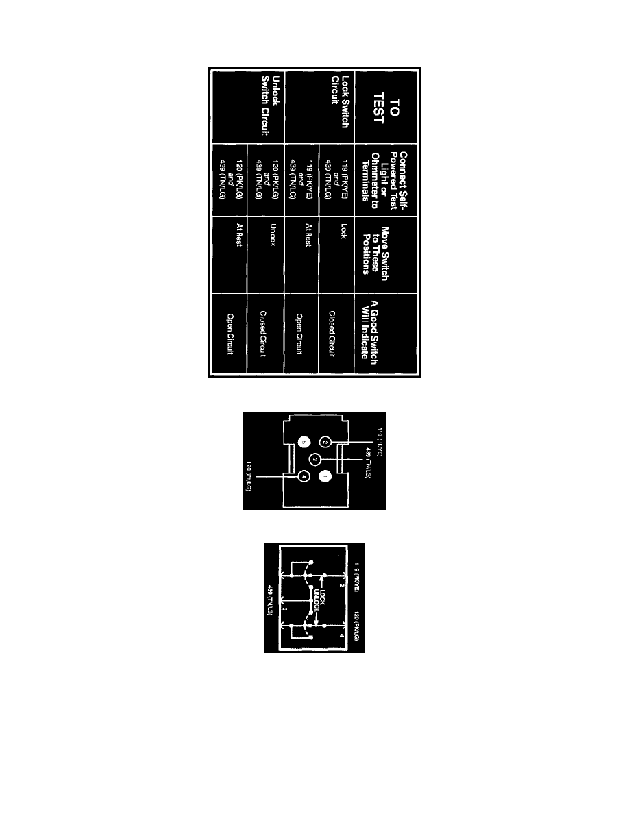
Liftgate Lock Switch
Component Testing Procedure
Terminal - Liftgate Lock Switch
Schematic - Liftgate Lock Switch
1. Use a self-powered test lamp or an ohmmeter to test the liftgate lock/unlock switch.
2. With the liftgate lock/unlock switch in the neutral position, there should not be resistance between Terminals 3 and 4 and Terminals 2 and 3.
Terminal 3 should be disconnected from all other terminals.
3. When the raised portion of the liftgate lock/unlock switch (L) is pressed, there must be resistance between Terminals 2 and 3. Terminal 4 should
be disconnected from all other terminals.
4. When the depressed portion of the liftgate lock/unlock switch (U) is pressed, there must be resistance between Terminals 3 and 4. Terminal 2
should be disconnected from all other terminals.
5. If the liftgate look/unlock switch does not test as stated, replace the liftgate lock/unlock switch.