
Sable V6-3.0L VIN U (1999)
6. Clean burrs from alignment plate and paint exposed metal on front spring and shock tower and plate.
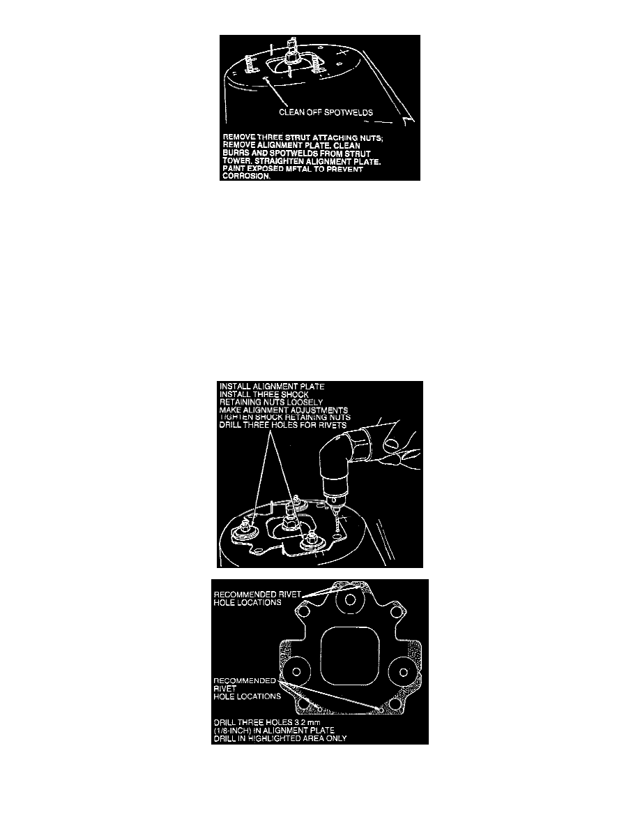
REMOVE THREE STRUT ATTACHING NUTS REMOVE ALIGNMENT PLATE. CLEAN BURRS AND SPOT WELDS FROM STRUT
TOWER. STRAIGHTEN ALIGNMENT PLATE PAINT EXPOSED METAL TO PREVENT CORROSION.
7. Install alignment plate.
8. Loosely install three front shock absorber mount nuts.
9. NOTE: Caster measurements must be made on the LH side by turning the LH wheel through the prescribed angle of sweep and on the RH side by
turning the RH wheel through the prescribed angle of sweep.
NOTE: When using alignment equipment designed to measure caster on both the RH and LH side, turning only one wheel will result in a
significant error in the caster angle for the opposite side. Make alignment-camber/caster adjustments.
10. Tighten three front shock mounting bracket nuts to 30 - 40 Nm (22 - 30 ft. lbs.).
11. .CAUTION: To prevent damage, do not drill deeper than 9.6 mm (3/8 inch) into shock tower.
Drill three 3.2 mm (1/8 inch) holes through alignment plate and paint exposed metal.
CAUTION: DO NOT DRILL DEEPER THAN 9.6mm (3/8 INCH].