
Sable V6-3.0L VIN U (1999)
using the following service procedure:
1. Inspect rear suspension for damage. Replace any damaged components before continuing.
2. Measure and record vehicle rear wheel alignment settings for LH camber, RH camber, LH toe and RH toe.
a. If vehicle is in specification for camber but out of specification for toe, reset toe to nominal specification of +0.06 degrees toe-in for each
individual wheel.
3. Obtain Rear Camber Adjustment Kit E7DZ-5K751-A or equivalent.
4. Raise vehicle using frame hoist.
5. Remove stabilizer bar bracket from outboard ends of lower rear suspension arm and bushing and rear stabilizer bar.
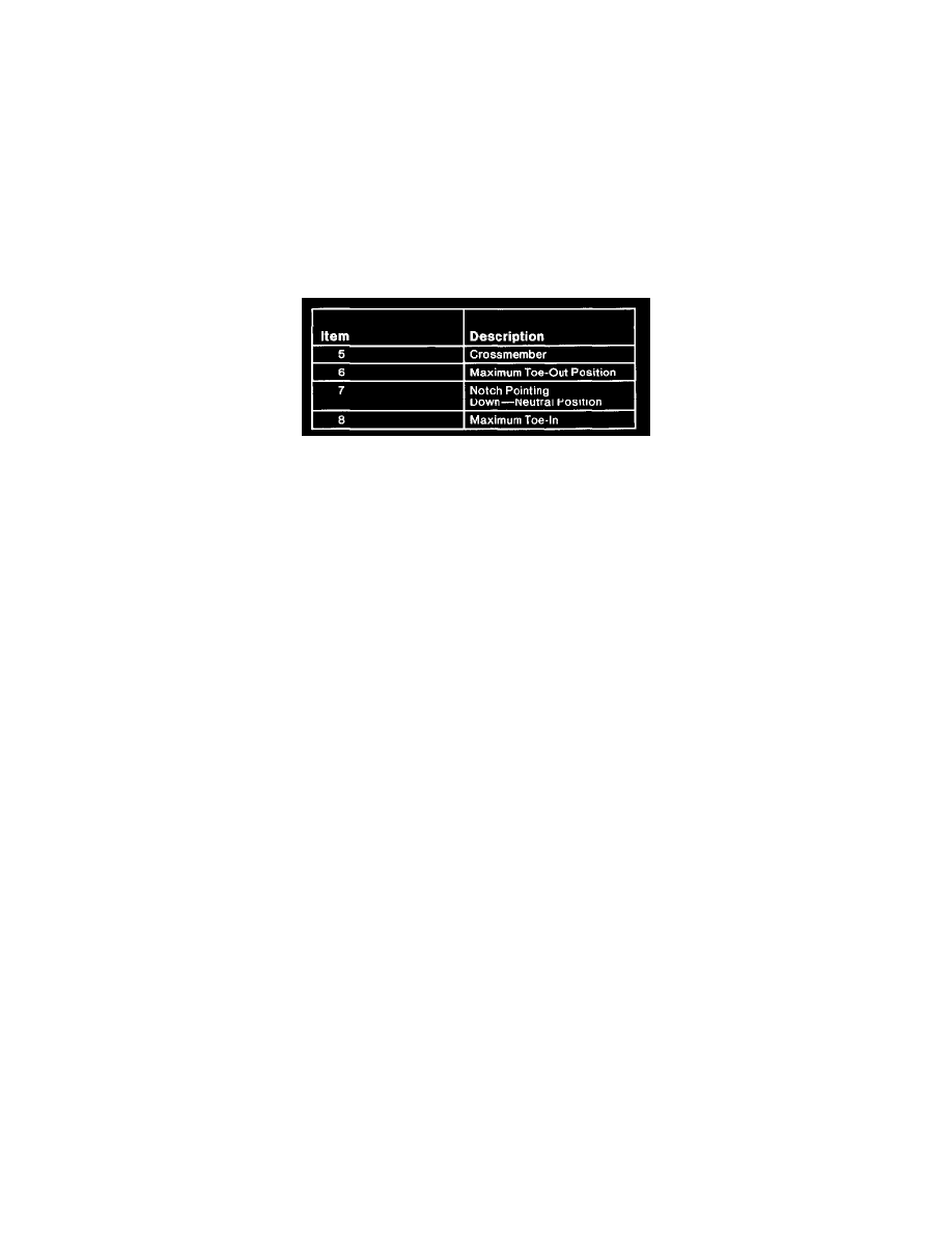
6. Remove parking brake cable retaining bracket from crossmember center bracket.
7. Place a floor jack with a wood block under lower rear suspension arm and bushing stamping midway between lower arm inner pivot bushing and
rear spring.
8. Remove and discard rear suspension arm and bushing inner pivot retaining nut.
9. Using floor jack, pre-load underside of lower arm. Remove and discard lower arm inner pivot bolt.
Part 2 Of 2
10. Using floor jack, slowly lower the rear suspension arm and bushing out of crossmember pocket until rear spring is completely relaxed. A pry bar
will be required to guide rear suspension arm and bushing toward outboard direction to clear crossmember stamping as arm is being lowered.
11. Using a 1/2-inch diameter tapered rotary file, elongate both rear suspension lower arm crossmember holes to the following dimensions:
a. If camber measurement from Step 2 was out-of-specification in the negative direction, elongate hole horizontally on inboard side until overall
slot length measures 24 mm (0.94 inch).
b. If camber measurement from Step 2 was out-of-specification in the positive direction, elongate hole horizontally on outboard side until overall
slot length measures 16 mm (0.63 inch).
12. Using floor jack, raise lower rear suspension arm and bushing back up into crossmember pocket.
13. Install kit inner pivot cam bolt from front side of crossmember. As cam bolt is being installed, the two kit tab washers are to be installed on bolts
so one washer is trapped between each end of inner pivot bushing inner sleeve and inside surface of crossmember pocket.
14. Place kit cam washer and nut on bolt, position tab washers to be in contact with crossmember bracket and tighten nut to 54 - 74 Nm (40 - 55 ft.
lbs.).
15. Repeat Steps 7 through 14 for opposite side of vehicle.
16. Reinstall stabilizer bar brackets and parking brake cable bracket. Tighten stabilizer bar bracket to-lower arm retaining bolts to 19 - 26 Nm (14 - 19
ft. lbs.).
17. Align rear wheels.
Toe, Rear
1. Place vehicle on alignment rack.
2. Loosen bolt attaching lower rear suspension arm and bushing to rear wheel spindle.
3. Rotate alignment cam until required toe setting is obtained.
4. Tighten lower rear suspension arm and bushing to rear wheel spindle nut to 68 - 92 Nm (50 - 67 ft. lbs.).