
Sable V6-3.0L VIN U (1999)
Tie Rod End: Service and Repair
Inner
Tie Rod and Bellows
Special Tool
Disassembly
1. Remove power rack and pinion steering gear.
2. NOTE: Drill out mounting holes in holding fixture with a 9/ 16 inch drill to allow the power rack and pinion steering gear assembly mounting
bolts to fit.
Mount power rack and pinion steering gear assembly in Bench Mounted Holding Fixture 307-003 (T57L-500-B).
3. Remove tie rod ends.
4. CAUTION: Use care not to damage bellows. If bellows are damaged, this will allow contamination into the power rack and pinion
steering gear and cause leakage.
Remove four clamps retaining bellows to power rack and pinion steering gear and front wheel spindle tie rods. Discard clamps if damaged or
excessively corroded.
5. NOTE: Power rack and pinion steering gear does not use rivets or roll pins between the front wheel spindle tie rod and rack.
Remove tie rod bellows along with power steering gear rack tube.
6. NOTE: The adjustable wrench should absorb the rod assembly torque, not the pinion inside the power rack and pinion steering gear.
Position power rack and pinion steering gear so that several steering gear teeth are exposed. Hold steering gear with an adjustable wrench on end
teeth only, while loosening front wheel spindle tie rod.
Assembly
1. NOTE: The adjustable wrench should absorb the rod assembly torque, not the pinion inside the power rack and pinion steering gear.
Expose several steering gear teeth and hold with adjustable wrench.
2. Tighten each front wheel spindle tie rod separately to 90 - 110 Nm (67 - 81 ft. lbs.).
3. Thoroughly clean steering gear and steering gear housing bore of any foreign material. Any abrasive material is extremely harmful to
high-pressure oil seals.
4. Apply Steering Gear Grease C3AZ-19518-A meeting Ford specification ESB-M1C 119-A to groove in connecting rods where bellows clamp to
front wheel spindle tie rod and uniformly to inner diameter of tie rod bellows before installation. This allows for toe-in adjustment without twisting
bellows.
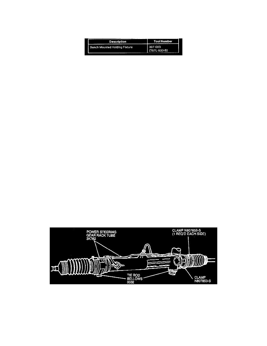
5. Install tie rod bellows and power steering gear rack tube. Make sure tie rod bellows is positioned as shown. Make sure tie rod bellows is seated in
groove in front wheel spindle tie rod. Position clamps as shown.
6. Install bellows retaining clamps and position screw axis as shown. Tighten to 2 - 3 Nm (18 - 26 inch lbs.).
7. Install new clamps retaining tie rod bellows to tie rod ends.
8. Apply Silicone Dielectric Compound D7AZ-19A331-A or equivalent meeting Ford specification ESE-M1C171-A to front wheel spindle tie rod
threads.