
Sable AWD V6-3.5L (2008)
Principles of Operation
PRINCIPLES OF OPERATION
NOTE: The smart junction box (SJB) is also known as the generic electronic module (GEM).
Vehicle communication utilizes both International Standards Organization (ISO) 9141 and controller area network (CAN) communications. ISO 9141 is
used for diagnostic use only, and CAN is a method for transferring data among distributed electronic modules via a serial data bus.
The vehicle is equipped with 3 module communication networks:
-
ISO 9141
-
Medium speed (MS) CAN
-
High speed (HS) CAN
ISO 9141 Communications Network
The ISO 9141 communications network is a single wire network. The ISO 9141 communications network does not permit intermodule communication
and is used for diagnostic use only. The only module on the ISO 9141 network is the parking aid module. When the scan tool communicates to the
parking aid module, the scan tool must request all information, the module cannot initiate communications.
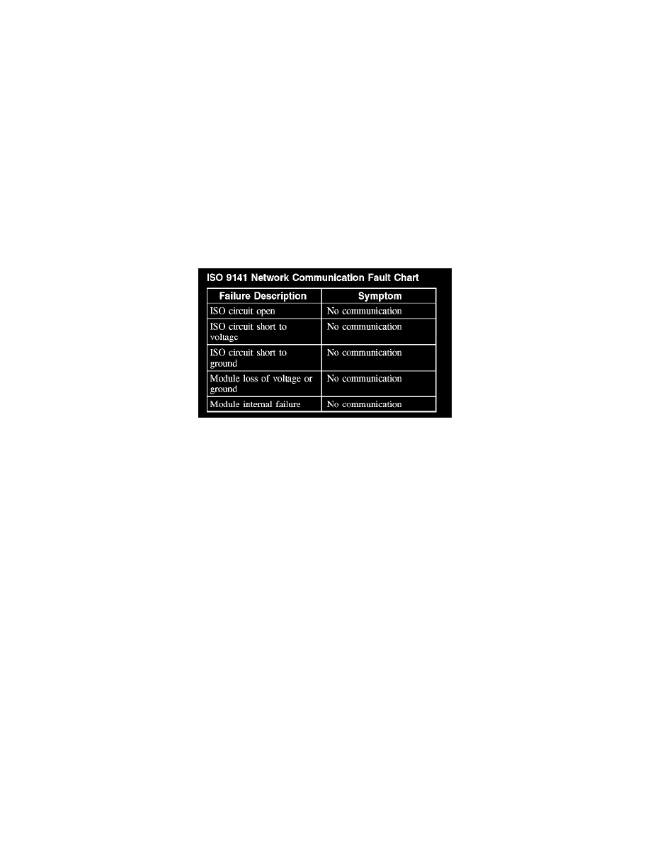
The following fault chart describes the specific ISO 9141 network failures and their resulting symptom:
ISO 9141 Network Communication Fault Chart
MS-CAN
The MS-CAN network uses an unshielded twisted pair cable of data (+) and data (-) circuits. The data (+) and the data (-) circuits are each regulated to
approximately 2.5 volts during neutral or rested network traffic. As bus messages are sent on the data (+) circuit, voltage is increased by
approximately 1.0 volt. Inversely, the data (-) circuit is reduced by approximately 1.0 volt when a bus message is sent. Multiple bus messages can be
sent over the network CAN circuits allowing multiple modules to communicate with each other. The MS-CAN is used for the instrument cluster, the
smart junction box (SJB), the driver seat module (DSM), the audio unit, the satellite radio receiver, the digital versatile disc (DVD) player, the power
liftgate module, and the electronic automatic temperature control (EATC) or electronic manual temperature control (EMTC) module communications,
and designed for general information transfer. The MS-CAN network will not communicate while certain faults are present, but will operate with
diminished performance with other faults present. The MS-CAN bus may remain operational when 1 of the 2 termination resistors are not present.
In the event that one of the 2 network circuits (MS-CAN + or MS-CAN -) becomes open to a module on the network, unreliable network
communication to all modules on the network may result. The module to which the network circuit is open may repeatedly send network messages
indicating there has been partial data received. This type of message is referred to as a negative-acknowledge (NACK) message. Repeated NACK
messages may "load" the network with too much activity causing intermittent no communication to other network modules and/or the scan tool.
The following fault chart describes the specific MS-CAN network failures and their resulting symptom: