
Topaz L4-140 2.3L CFI (1985)
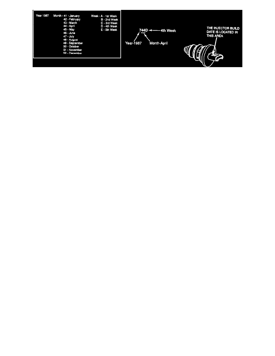
FIGURE 1
3.
Refer to Figure 1, below. Look at the side of the injector electrical connector for the build date. (Three numbers followed by one letter). Using the
following chart, interpret the injector build date 744D as per example.
4.
Refer to the following chart to determine if the injector requires replacement.
-
Replace injectors with build dates prior to the following dates.
-
DO NOT replace injectors with build dates on or after the following dates.
Engine Size
Injector Build Date
Injector Color-Code
2.3L CFI (Base)
744D
Blue
2.3L CFI HO
742D
Green
1.9L CFI
743B
Gray
5.
Refer to the Modification Procedure Summary (Attachment I, Page 1).
Exhibit 2 Injector Removal and Installation Procedure
Disassembly
^
Disconnect battery for 5 minutes.
^
Remove the fuel injector retaining screw and retainer.
^
Remove the injector assembly and the lower O-ring (the O-ring may stay on the injector seat).
Caution:
Be sure to remove the lower O-ring carefully (do not use a screwdriver because it could damage the throttle body injector seat).
Assembly
-
Clean the throttle body O-ring seat.
-
Lubricate the new lower O-ring and the injector seat area with clean engine oil.
Caution:
Do not use transmission oil.
^
Install the lower O-ring on the throttle body seat.
^
Lubricate the upper O-ring on the injector with clean engine oil.
^
Install the injector by centering and applying a steady downward pressure wfth a slight rotational force.
^
Install the injector retainer and retaining screw.
^
Tighten the retainer screw to 2.0-2.5 N-m (18-22 in.lbs).
Injector Leak Check Procedure
^
Reconnect the battery.
^
Turn the ignition key to the "ON" position for 5 seconds.