
Topaz L4-140 2.3L CFI (1985)
Step 3.
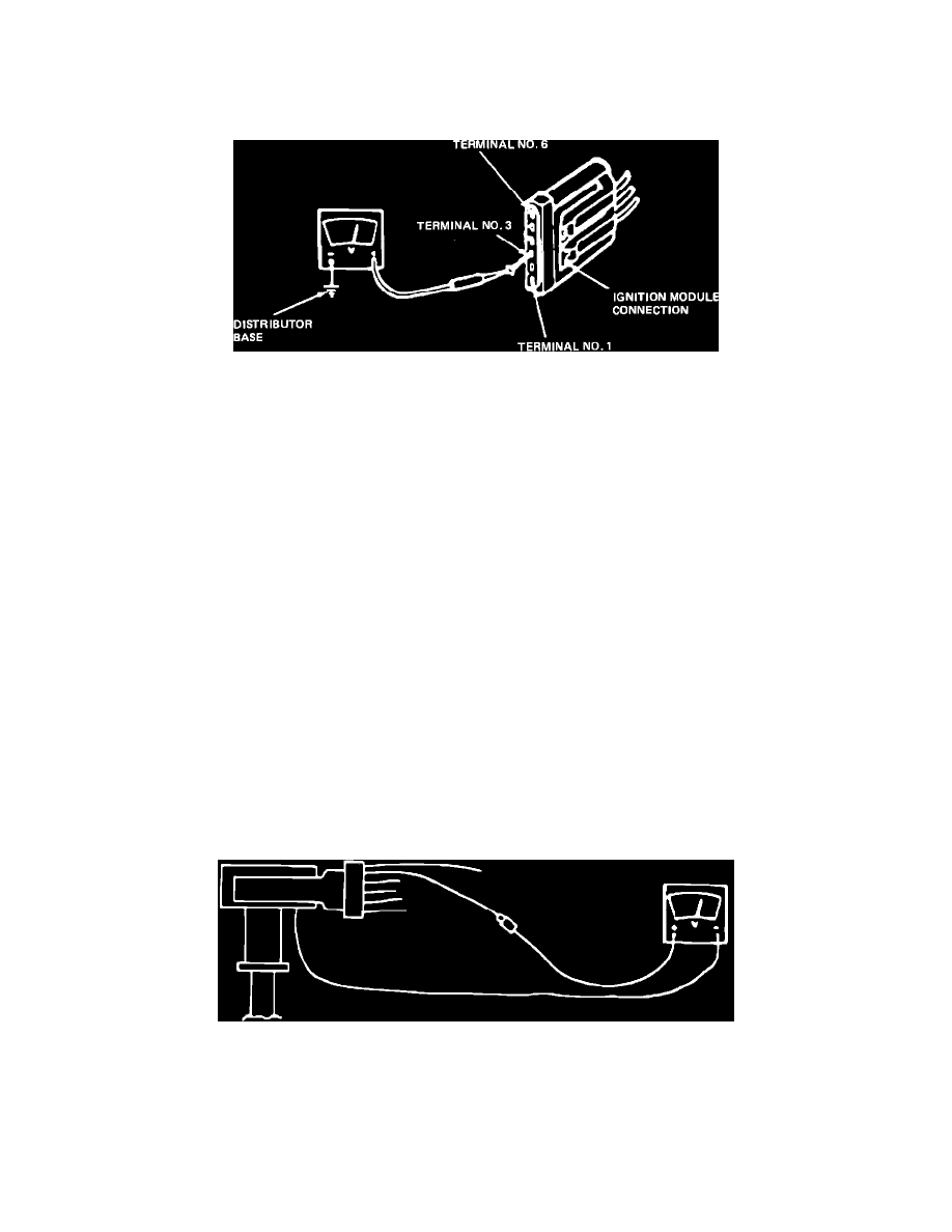
Attach negative (-) VOM lead to distributor base.
Step 4.
Measure battery voltage (Positive + VOM lead to
positive battery terminal).
Figure 21 - Terminal Voltage Measurement
Step 5.
Measure the Number 3 terminal voltage by
attaching VOM to small straight pin inserted into ignition module connector terminal (Figure 21) and turning ignition switch to
the run position.
Yes
Replace the stator
CAUTION: Do not allow straight pin to contact electrical assembly. ground. No
Inspect for faults in
Step 6.
Is the voltage at Terminal No. 3 greater than 90%
wiring harness and
of battery voltage (.9 X's Step 3)?
connectors?
Refer to vehicle wiring
NOTE:
After this test, turn the ignition switch diagram for appropriate off, remove the straight pin and reconnect the
circuit.
wire to "S" terminal of starter relay and
Damaged or worn igni-
ignition module.
tion switch. Refer to Shop
Manual, Group 33.
TEST 4
Step 1.
Turn the ignition switch to the "OFF" position.
Step 2.
Attach the negative (-) VOM lead to the distributor
base.
Step 3.
Start the engine and measure the battery voltage at
1200-1500 RPM (Positive + VOM lead to positive battery terminal).
Figure 20 - Voltage Measurement
Step 4.
Measure the voltage on the TFI module side of the
SPOUT connector (Figure 20) at 1200-1500 RPM.
Yes
Go to Test 5
Step 5.
Is the voltage at the TFI module between 40% and
No
Replace the stator
60% of battery voltage from Step 3?
assembly.
NOTE:
Stator condition must exist when test is performed. If not, test is inconclusive.
WILL NOT START, HARD START OR STARTS BUT WILL NOT RUN