
Topaz L4-140 2.3L CFI (1985)
13.
Wipe the rear end bearing surface of the rotor shaft with a clean, lint-free cloth.
14.
Position the rear housing and stator assembly over the rotor and align the scribe marks made during disassembly.
15.
Seat the machined portion of the stator core into the stop in both end housings and install the housing through bolts. Tighten the bolts to 4.1-6.7
N-m (35-60 in.lbs.). Spin the rotor to check for free movement.
Figure 13
16.
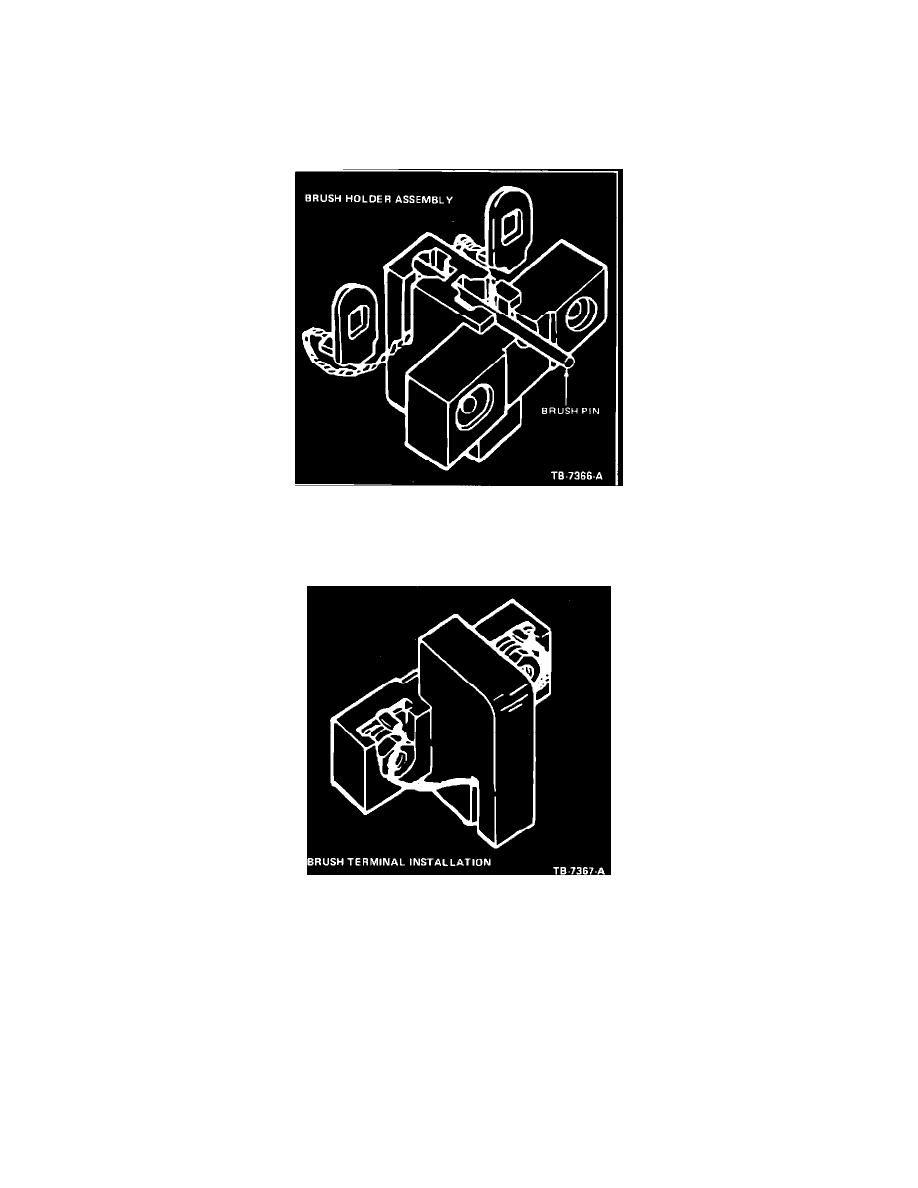
Install the springs and brushes in the brush holder. Hold the brushes in place by inserting a 35 mm (1-3/8 inch) long piece of stiff wire into the
brush holder pin hole. (Figure 13).
Figure 14
17.
Position the two nut and washer assemblies into the retaining slots in the brush holder. Tip the holder back slightly so that the nut and washer
assemblies fall to the nut side of the slots. Insert the brush terminals past the washers and into the slots (Figure 14).