
Topaz L4-140 2.3L CFI (1985)
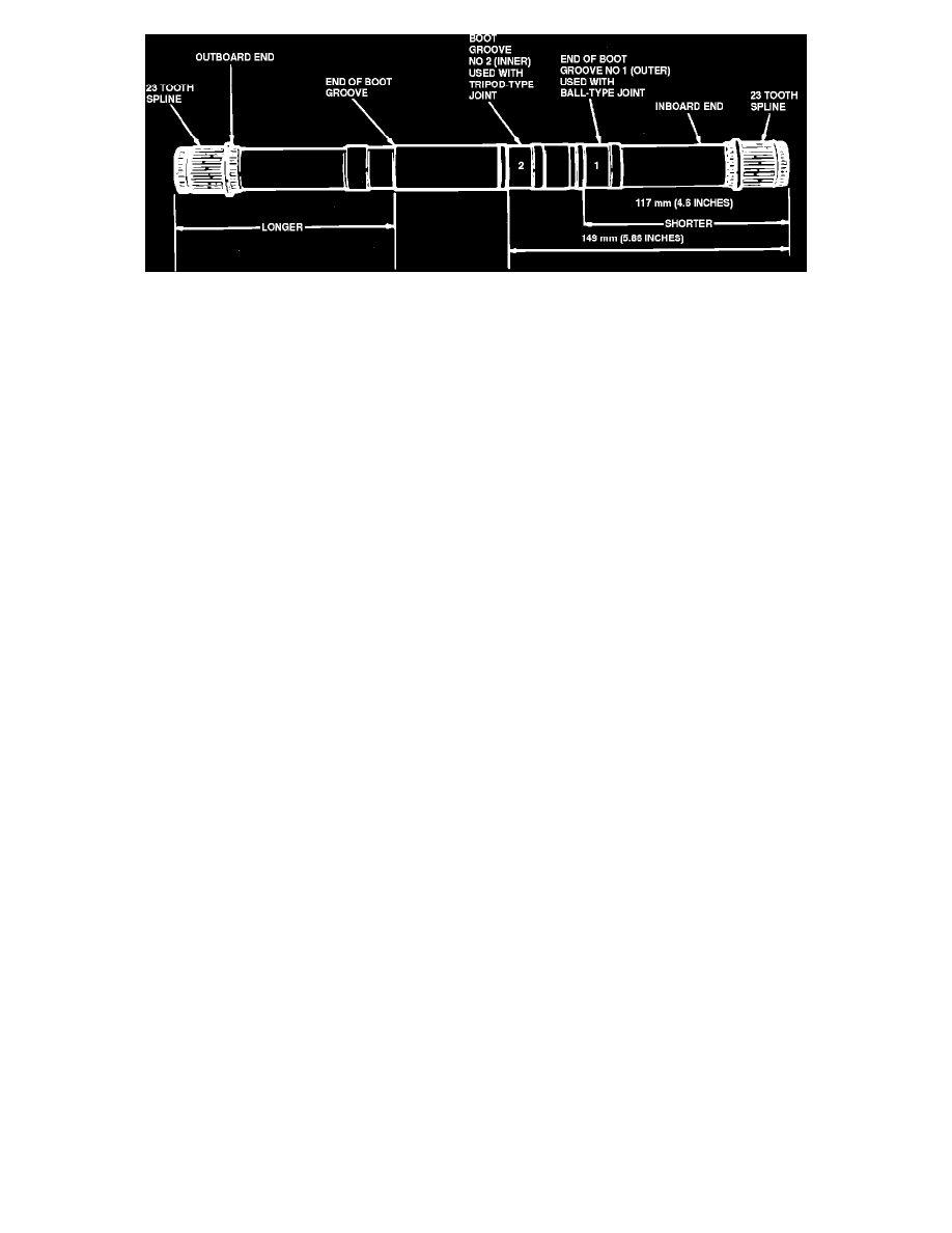
Fig. 8 Interconnecting Shaft. 1989-90
Inboard Constant Velocity Joint & Boot, 5 Speed Manual Transmission
1.
Move circlip and stop ring back into their respective grooves on shaft. Lefthand interconnecting shaft is symmetrical and inboard and
outboard constant velocity joints may be installed on either end. Righthand interconnecting shaft is non-symmetrical and care must be
taken so that inboard and outboard constant velocity joints are correctly installed, Figs. 19 and 20.
2.
Install constant velocity joint boot, if removed. Ensure that boot is seated in groove, then install clamp securely but not too tight.
3.
Install new circlip in groove nearest end of shaft. To avoid over-expansion or twisting of circlip, start one end in groove and work circlip over stub
shaft end and into groove.
4.
Fill boot with 45 grams of grease and fill outer race with 90 grams of grease. Use only lubricant E2FZ-19590-A or equivalent.
5.
Push inner race and bearing assembly into outer race by hand.
6.
Install ball retainer into groove inside outer race.
7.
With boot positioned upward toward end of shaft, install constant velocity joint using suitable hammer. Ensure that splines are aligned before
hammering constant velocity joint onto shaft.