
Topaz V6-182 3.0L (1992)
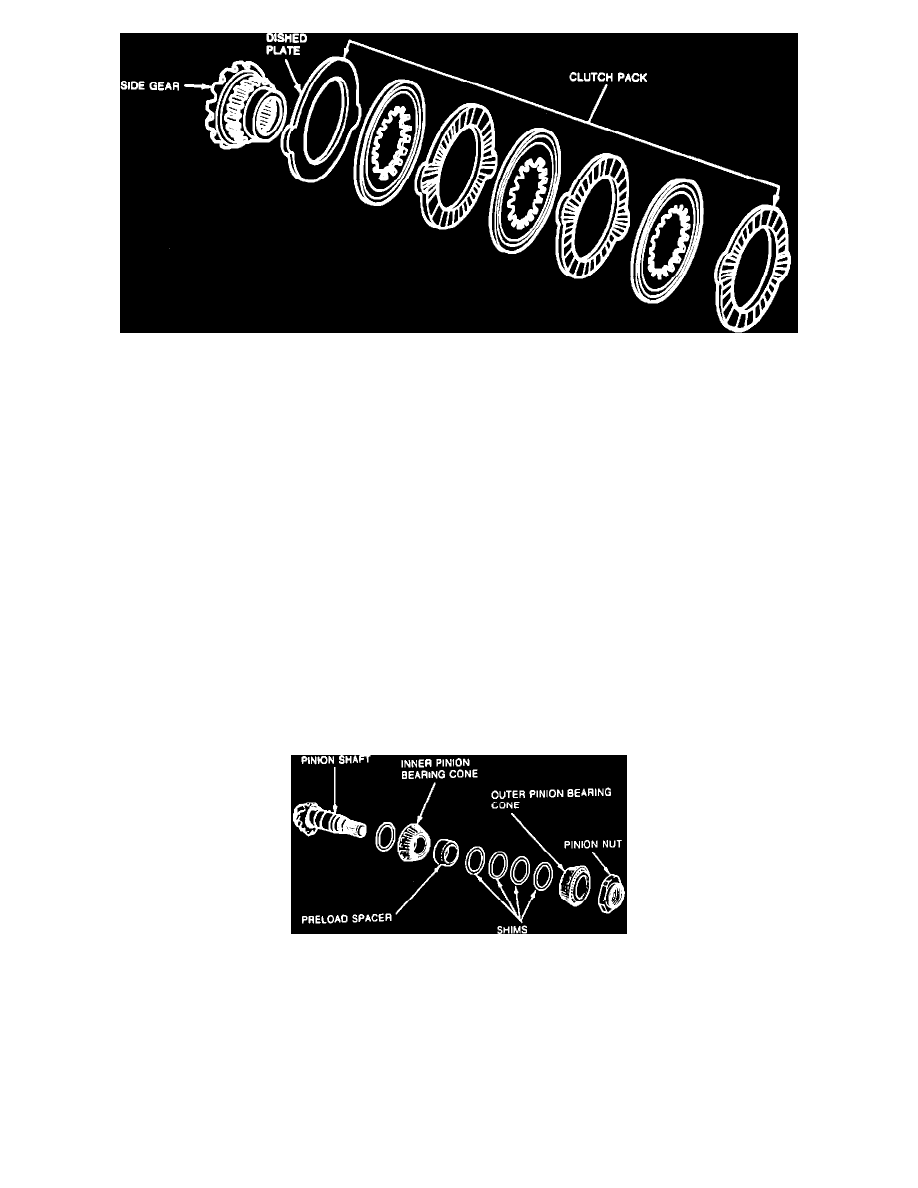
Fig. 8 Clutch Pack & Side Gear Assembly
32.
Remove tool, clutch packs and side gears, Fig. 8. Inspect all components for wear or damage, replace components, if necessary.
33.
Lubricate clutch plates and discs with lubricant C8AZ-19B546-A or equivalent. Assemble lefthand clutch pack and side gear assembly. Install
clutch pack and side gear into differential case. Ensure clutch pack retainers are aligned in the differential case.
34.
Turn differential case over and assemble righthand clutch pack and side gear assembly. Install righthand side gear and clutch pack into differential
case and hold in position. Ensure clutch pack retainers are aligned in the differential case.
35.
Install tool No. D80L-630-1 or equivalent into lefthand side gear. Install forcing screw of tool, through differential case and install tool No.
T87P-4205-A or equivalent. Position case on inner yoke shaft. Lightly tighten forcing screw.
36.
Install differential assembly over yoke shaft.
37.
Position pinion gears into windows of differential case so that they mesh with side gear teeth. Hold pinion gears in position. Ensure pinion gears
are 180° apart so they will correctly align with pinion shaft bore.
38.
Insert tool No. T87P-4205-B or equivalent into pinion shaft bore and turn differential case. This will cause pinion gears to engage side gears and
``walk'' into differential case. Rotate differential case until pinion mating shaft holes are aligned exactly with holes in pinion gears. It may be
necessary to tighten or loosen the forcing screw of tool. Allow pinion and side gears to rotate.
39.
Tighten forcing screw of tool, until side gears become loose. Lubricate and install differential pinion thrust washers. Ensure thrust washers align
exactly with holes and remove tools.
40.
Install differential pinion shaft from roll pin hole side of case. Ensure to align pin hole in shaft with roll pin hole in case.
41.
Install roll pin.
42.
Remove and discard pinion to adapter O-ring seal.
43.
Remove pinion nut using suitable tools. Tap pinion using a suitable hammer to remove it from housing. Save bearing preload spacer and preload
shim. Remove outer pinion bearing cone.
44.
Remove inner pinion bearing cone.
Fig. 9 Inner & Outer Cone Assembly
45.
Remove inner and outer pinion bearing cups, Fig. 9.
46.
Remove ring gear side differential bearing cup.
47.
Place differential bearing cap in a suitable vise. Remove bearing cap differential bearing cup.
48.
Wipe clean pinion and differential bearing bores. Install inner and outer pinion bearing cups.
49.
Install tools Nos. T76P-4020-A11, T80T-4020-F43, T76P-4020-A14 and T87P-4020-A or equivalents into inner pinion bearing bore of carrier.
50.
Place gauge bar part of tool kit No. T87P-4020-A or equivalent into bearing bore.
51.
Install bearing attaching cap with O-ring from gauge bar tool part of tool kit T87P-4020-A or equivalent in cap bore. Tighten retaining screws
slightly.
52.
Select the thickest feeler gauge or shim(s) that will enter between the pinion gauge block tool and gauge bar. The feeler gauge fit should be a slight