
Topaz FWD L4-140 2.3L CFI (1987)
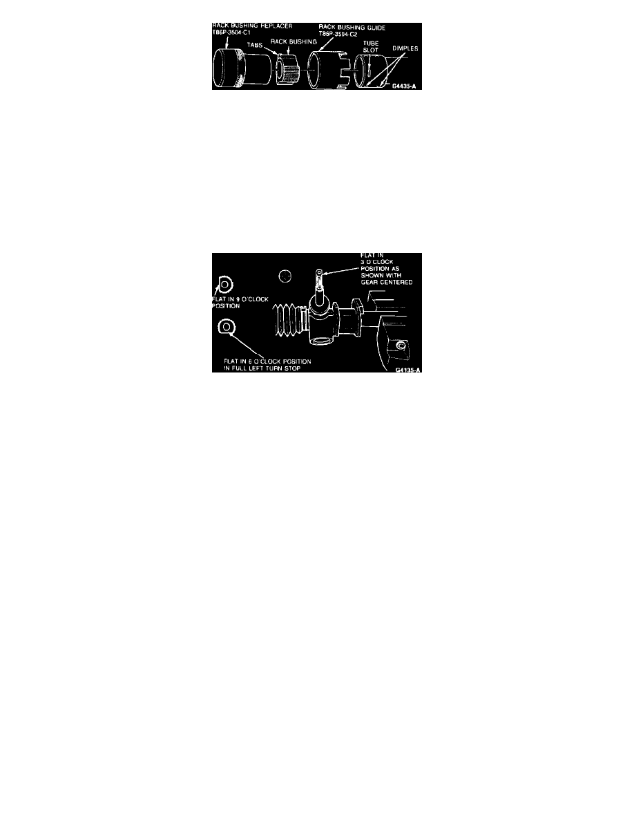
Fig. 3 Rack bushing guide alignment
Assembly
1.
If rack bushing was not removed, proceed to Step 7.
2.
Align three slots of Rack Bushing Guide T86P-3504-C2 or equivalent over dimples in rack tube Fig. 3. Align extra slot exactly over one of the
tube slots.
3.
Lubricate new rack bushing outer diameter with steering gear grease C3AZ-19578-A or equivalent.
4.
Insert new rack bushings into tool so tabs align with grooves in tool. Tabs must be up (away from rack housing).
5.
Push bearing into rack tube with tool No. T86P-3504-C1 or equivalent using hand pressure until tool bottoms. Remove guide tool. Re-apply hand
pressure with replacer tool to fully seat tabs in slots, if necessary. Use only enough force to fully engage tabs in slots.
6.
Inspect installation of rack bushing to ensure tabs are engaged into slots. If tabs are not properly positioned, dislodgement of bushing may occur.
7.
Fill rack teeth spacers with steering gear grease C3AZ-19578-A or equivalent. Coat remainder of rack with light coat of grease.
Fig. 4 Pinion flat positioning
8.
Pack pinion needle bearing with steering gear grease C3AZ-19578-A or equivalent. Pack some grease into cavity inboard of rack bushing. Also,
lightly coat inner diameter of rack bushing with grease.
9.
Install rack into housing from left end (pinion end) and center load slot in pinion bore.
10.
Pack pinion teeth and coat needle bearing journal with steering gear grease C3AZ-19578-A or equivalent. Pack pinion ball bearing with grease.
11.
Install pinion shaft and bearing assembly from bottom through load slot in rack.
12.
Install pinion plug and torque to 53---73 ft. lbs.
13.
Install left tie rod assembly to rack. Seat it against rack but do not tighten at this time. This establishes the left turn stop position of the rack.
14.
Mount gear housing in vise with pinion in approximately in-vehicle position. Hold pinion with flat in 9 o'clock position, Fig. 4, while pushing
rack into housing. Jiggle rack to engage rack to pinion and to start rack into rack bushing. Push rack all the way in. The input shaft flat should stop
in the 6 o'clock position when the left ball joint contacts the housing (full left turn stop). Repeat the procedures at the load slot, deviating from the
9 o'clock starting position, if necessary, until pinion flat ends up in 6 o'clock position with rack pushed in to full left turn stop.
15.
Install tie rod assembly to rack but do not tighten.
16.
Coat yoke at rack contact surface with steering gear grease C3AZ-19578-A or equivalent. Also fill groove on the same surface with grease. Install
yoke, yoke spring and yoke plug. Tighten plug until most of the play in the rack is taken out. Do not set yoke mesh load at this time.
17.
Check pinion shaft flat position with gear centered. Gear is on center when pinion is an equal number of turns from each stop. If flat is not
in the 3 o'clock position within 10°, remove right tie rod assembly and go back to step 14. Do not remove yoke plug when repeating Step
14. The pinion only has 4 teeth, so the flat can only be in one of 4 positions, 90° apart.
18.
Remove yoke plug and restart the threads {1-2} to 1 turn. Apply 3 drops of hydraulic sealant to plug threads equally spaced.
19.
Tighten yoke to 40 inch lbs.
20.
With tool No. T86P-3504-B or equivalent, slowly turn pinion {1-2}turn in each direction from center and return to center. Repeat twice and check
peak torque within {1-4} turn of center. The peak torque must be a minimum of 15 inch lbs. in both directions. If peak torque is not within limits,
inspect yoke bore threads for burrs and repeat procedure.
21.
Back off the yoke plug {]1-4} turn.
22.
Measure pinion torque across center to ensure it is 4.6---13.2 inch lbs.
23.
Stake plug in three places equally spaced. Each stake should be midway between original stakes.
24.
Pack steering gear grease into space above needle bearing between input shaft and housing, about {2-3} full. Leave room for input shaft seal to be
installed.
25.
Coat new input shaft seal lip with multi-purpose long-life lubricant C1AZ-19590-B or equivalent. Press seal in with tool No. T81P-3504-Y or
equivalent size washer ({5-8} to {3-4} ID), using hand pressure. Inspect seal to verify that it is flush with top of housing and is not twisted.
26.
Stake pinion plug in two places midway between original stakes.
27.
Fill the plastic dirt extruder with long life lubricant C1AZ-19590-B or equivalent and hand install until bottomed on gear housing. Use a twisting
motion to force the dirt excluder onto the larger ground diameter. Wipe off excess grease and inspect dirt extruder to ensure that it is located on