
Tracer L4-116 1.9L SOHC (1991)
Brake Warning Indicator: Description and Operation
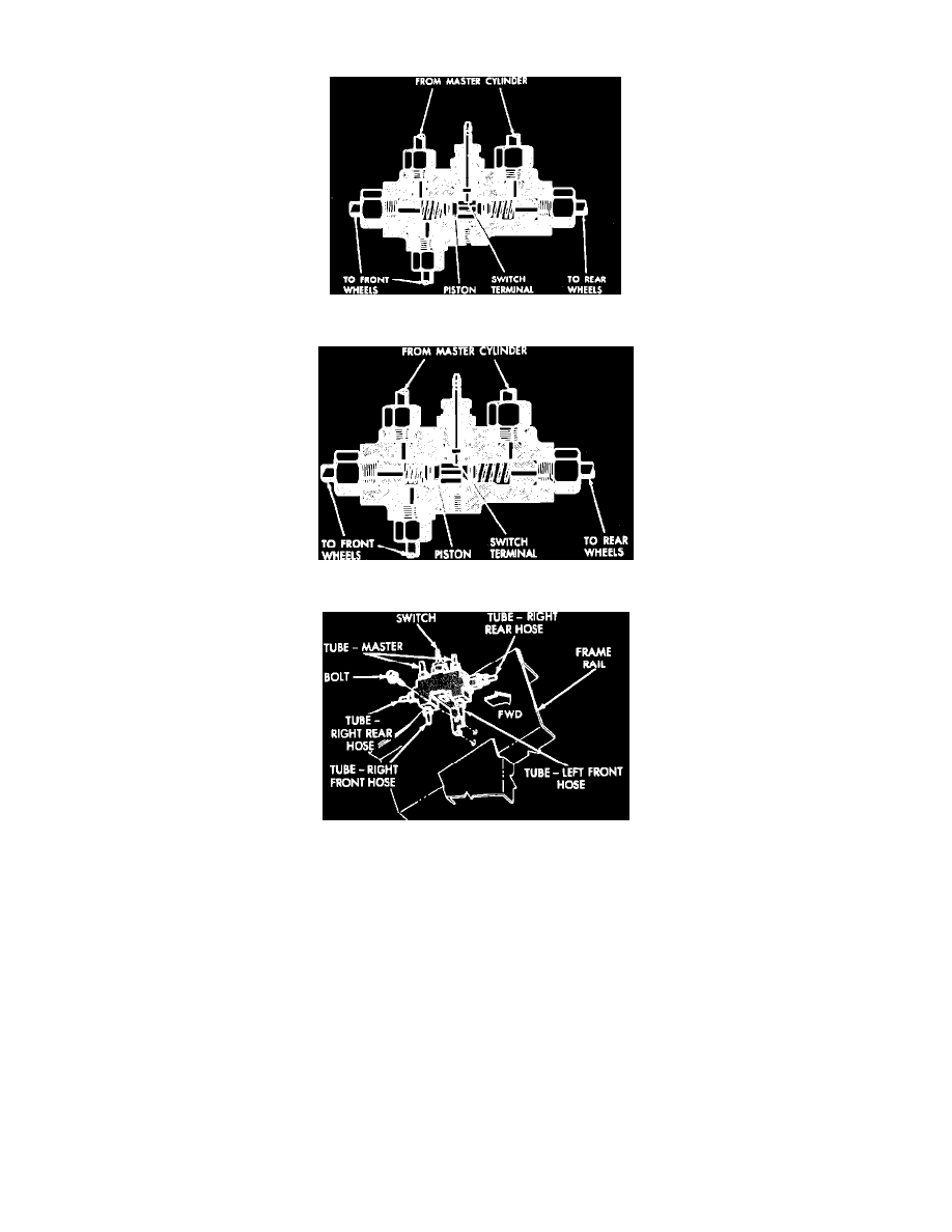
Fig. 18 Brake Distribution Switch (Normal)
Fig. 19 Brake Distribution Switch (Failed)
Fig. 20 Typical Brake Distribution Switch Used In Diagonally Split Brake Systems
This switch assembly, which is used on some diagonally split brake systems, is connected to the outlet ports of the master cylinder and also to the
brake warning light that warns the driver if either the primary or secondary brake system has failed.
When hydraulic pressure is equal in both primary and secondary brake systems, the switch remains centered, Fig. 18. If pressure fails in one of the
systems, hydraulic pressure moves the piston toward the inoperative side, Fig. 19. The shoulder of the piston contacts the switch terminal, providing a
ground and lighting the warning lamp.
Fig. 20 shows a brake distribution valve and switch used on some diagonally split brake system applications.