
Tracer L4-116 1.9L SOHC (1991)
Stabilizer Bar: Service and Repair
Front
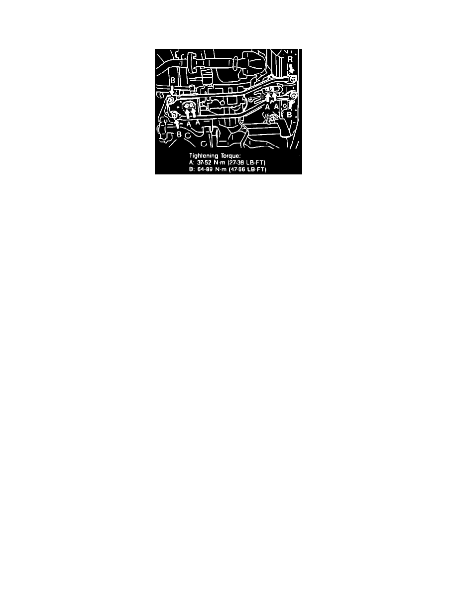
Fig. 2 Crossmember Bolt Torquing Sequence
1.
Support engine with three bar engine support No. D88L-6000-A or equivalent, then raise and support vehicle.
2.
Remove front wheels, then remove nuts securing steering gear mounting brackets.
3.
Position steering gear slightly forward, then remove stabilizer bar nuts, washers, bushings, sleeves and bolts from lower control arm.
4.
Remove rear crossmember nuts from rear transaxle mount and vehicle frame.
5.
Loosen front crossmember bolts and nuts from front transaxle mount and vehicle frame, then lower rear end of crossmember.
6.
Remove nuts and bolts securing chassis frame to vehicle frame, then lower chassis frame. Engine and transaxle mounts will support the chassis
frame when unbolting chassis frame from vehicle frame.
7.
Unbolt stabilizer bar from chassis frame and remove stabilizer bar from vehicle.
8.
Reverse procedure to install noting the following:
a. Torque stabilizer bar to chassis frame bolts to 32-43 ft. lbs.
b. Torque chassis frame to vehicle frame bolts to 69-93 ft. lbs.
c. Torque crossmember to vehicle frame and transaxle mounts as shown in Fig. 2.
d. Install stabilizer bar bolts, sleeves, bushings, washers and nuts and tighten so that .67-.75 inches of thread is showing.
e. Torque steering gear bracket nuts to 28-38 ft. lbs.