
Villager V6-181 3.0L SOHC VIN 1 EFI (1997)
2.
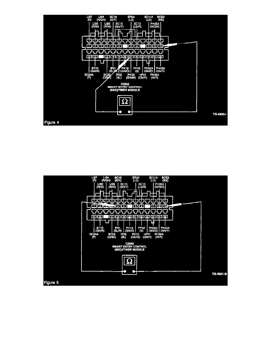
Using a Digital Volt-Ohm Meter (DVOM), operate the power door lock switches and check the door "lock" input signal between Pin 21 (GN/W)
and ground Pin 13 (BK). There should be continuity in the LOCK position and an open circuit in the UNLOCK and NEUTRAL positions (Figure
4).
3.
Using a DVOM, operate the power door lock switches and check the door "unlock" signal between Pin 20 (GN/O) and ground Pin 13 (BK). There
should be continuity in the UNLOCK position and an open circuit in the LOCK and NEUTRAL positions.
4.
Perform a wiggle test at the switch harness connector while operating the door lock switches.
5.
Check the front door power lock actuator internal switch circuits for possible shorts-to-ground or high resistance by testing continuity between Pin
5 (R/Y) and ground Pin 13 (BK) for the left door (Figure 5), and Pin 6 (GN/Y) and ground Pin 13 (BK) for the right door. Manually operate the
power lock actuator using the door lock knob. There should be 10 ohms or less in the UNLOCKED position, and 10,000 ohms or more in the
LOCKED position. Perform a wiggle test at the actuator harness connector while taking readings.
6.
If a resistance reading is excessive, low or fluctuates, isolate the cause to either the circuit wiring (repair as necessary), or the power lock actuator
(replace). If a short-to-ground is indicated, inspect the wiring harness around the armrest for possible chafing.
7.
For vehicles without anti-theft, proceed to Step 8. For vehicles with anti-theft, proceed to the Key Cylinder Lock/Unlock Signal Check.