
Villager V6-181 3.0L SOHC VIN 1 EFI (1997)
Hydraulic Control Assembly - Antilock Brakes: Service and Repair
REMOVAL
1. Disconnect the battery ground cable.
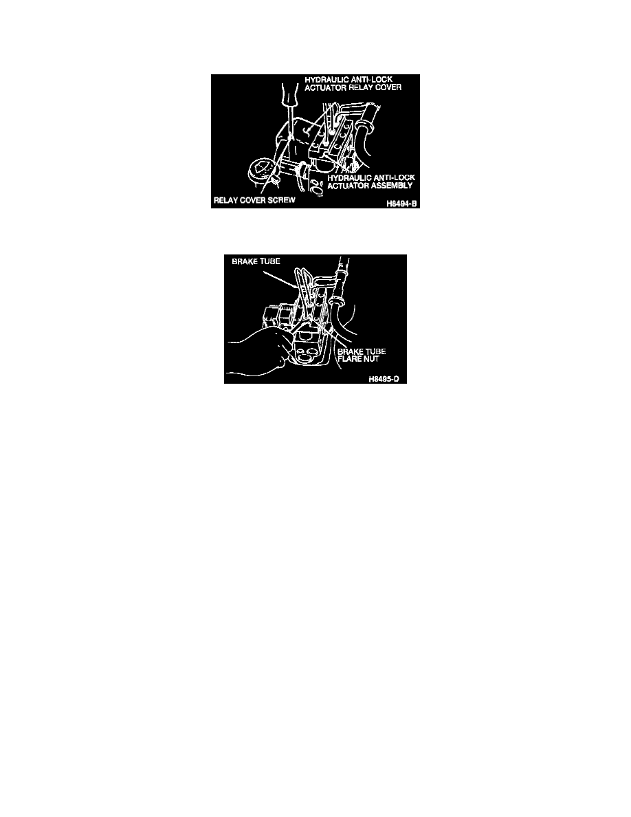
2. Remove the relay cover screw and remove the hydraulic anti-lock actuator relay cover.
3. Disconnect the hydraulic anti-lock actuator electrical connector.
4. Use a tube wrench to disconnect the six brake tubes from the hydraulic anti-lock actuator assembly.
5. Remove the three hydraulic anti-lock actuator assembly nuts from the isolators at the bracket.
6. Remove the hydraulic anti-lock actuator ground strap screw and remove the hydraulic anti-lock actuator assembly from the vehicle.
INSTALLATION
1. Install the hydraulic anti-lock actuator assembly in the vehicle, installing the hydraulic anti-lock actuator ground strap screw.
2. Install three hydraulic anti-lock actuator assembly nuts. Tighten the hydraulic anti-lock actuator assembly nuts to 11-15 Nm (124-133 inch lbs.).
3. Connect the six brake tubes to the hydraulic anti-lock actuator assembly by hand. Use a tubing wrench to tighten the brake tube flare nuts to 15-18
Nm (11-13 ft. lbs.).
CAUTION: Initially tighten all hydraulic brake tubes with your fingers. Failure to do so may result in damaged threads.
4. Connect the hydraulic anti-lock actuator electrical connector.
5. Install the hydraulic anti-lock actuator relay cover and the relay cover screw.
6. Connect the battery ground cable.
7. Bleed the brake system.