
Villager V6-181 3.0L SOHC VIN 1 EFI (1997)
Connecting Rod Bearing: Component Tests and General Diagnostics
Bore Gauge Method
Before installing the pistons, inspect the connecting rod bearing oil clearance.
1. Install the connecting rod bearings in the correct position on the connecting rod and connecting rod cap.
NOTE: Clean the connecting rod journals. Inspect the connecting rod journals for nicks, burrs, or roughness that would cause premature
connecting rod bearing wear.
2. Install the connecting rod cap and connecting rod cap nuts. Tighten the connecting rod cap nuts to 14-16 Nm (10-12 ft. lbs.). Turn the connecting
rod cap nuts an additional 60-65 degrees clockwise, or tighten to 38-44 Nm (28-33 ft. lbs.).
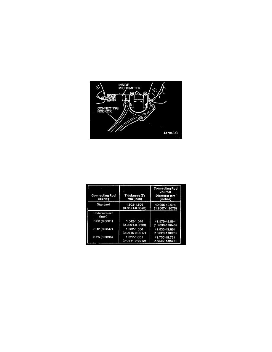
3. Use an inside micrometer to measure the connecting rod bore (with the bearings installed).
4. Use a micrometer to measure the diameter of the connecting rod journal.
5. Subtract the connecting rod journal measurement from the connecting rod bore measurement (with bearings installed) to obtain the connecting rod
bearing oil clearance.
6. Remove the connecting rod cap nuts and connecting rod cap.
7. The connecting rod oil clearances should be within 0.014-0.054 mm (0.0011-0.0022 inch). Maximum connecting rod oil clearance is 0.090 mm
(0.0035 inch).
8. If the connecting rod oil clearance is above specification, refer to the above chart for crankshaft grinding and undersize connecting rod bearings.
Plastigage Method
1. Clean the connecting rod journals. Inspect the journals for nicks, burrs, or roughness that would cause premature connecting rod bearing wear.
2. Install the connecting rod bearings in the correct position on the connecting rod and connecting rod cap.
3. Position the Plastigage(R) D81L-6002-B or equivalent across the top of the connecting rod journals.
4. Install the connecting rod cap and connecting rod cap nuts. Tighten the connecting rod cap nuts to 14-16 Nm (10-12 ft. lbs.). Turn the connecting
rod cap nuts an additional 60-65 degrees clockwise, or tighten to 38-44 Nm (28-33 ft. lbs.).
5. Remove the connecting rod cap nuts and connecting rod caps.
6. Measure the Plastigage(R) D81 L-6002-B or equivalent at each connecting rod journal.
NOTE: Do not rotate the crankshaft when measuring the oil clearances.
7. The connecting rod oil clearances should be within 0.014-0.054 mm (0.0011-0.0022 inch). Maximum connecting rod oil clearance is 0.090 mm
(0.0035 inch).