
Villager V6-181 3.0L SOHC VIN 1 EFI (1997)
Throttle Position Sensor: Adjustments
Without (NGS) Scan Tool
1. Remove the air duct.
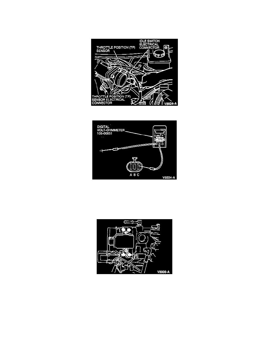
2. Disconnect the Throttle Position (TP) sensor electrical connector.
3. Connect Rotunda Digital Volt-Ohmmeter 105-R0051, or equivalent, between the TP sensor and ground as shown in image.
4. Turn the throttle lever to the wide open throttle position and check the reading on the volt-ohmmeter. The resistance should be approximately 4K
ohms.
5. Turn the throttle lever to the fully closed position. The resistance should be between 0.4K - 0.5K ohms. If the resistances are not within the
specifications, adjust the TP sensor as follows:
-
Loosen but do not remove the TP sensor screws.
-
With the throttle body in the closed position, adjust the TP sensor until the volt-ohmmeter reads between 0.4K - 0.5K ohms.
-
Turn the throttle lever to the wide-open position and check the resistance: The reading should be 4K ohms. If the resistance cannot be adjusted
to specification, the TP sensor must be replaced, and this procedure must be repeated on the new unit.
-
After the TP sensor readings meet specifications, tighten the TP sensor screws to 2.0-2.4 Nm (17-21 in lb).
7. Install the air duct.
8. Connect the TP sensor electrical connector.