
Villager V6-181 3.0L SOHC VIN 1 EFI (1997)
1.
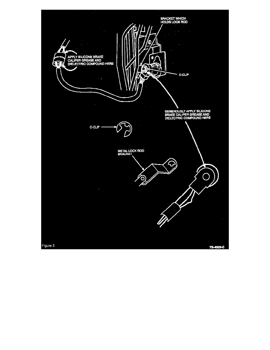
With both front door trim panels still removed, remove the C-clip located on the back side of the door lock cylinder. Lift the metal bracket, which
contains the lock rod, off the door lock cylinder. Generously apply dielectric grease to the back side of the key cylinder switch housing where the
bracket makes contact with the key cylinder switch and reassemble (Figure 3).
2.
Disconnect the driver's door key cylinder switch-to-harness connector located about 305 mm (12") from the door key cylinder. This is a 4-pin
connector with three (3) wires. Pack grease into the back side of this connector, especially into the blank connector to prevent water intrusion. Do
the same for the mating connector.
3.
Reverse Steps 1-2 in this procedure and Steps 1-4 in the previous Service Procedure to reassemble the doors, then proceed to the Power Door
Lock Signal and Wiring Check Procedure.
Power Door Lock Signal and Wiring Check Procedure
NOTE
WHEN USING AN OHMMETER TO CHECK CIRCUIT RESISTANCE, DISCONNECT THE VEHICLE'S BATTERY TO ENSURE AN
ACCURATE READING.
1.
Disconnect the SEC timer module connector C2032.