
Villager V6-201 3.3L SOHC VIN T SFI (1999)
Switch Positions (2)
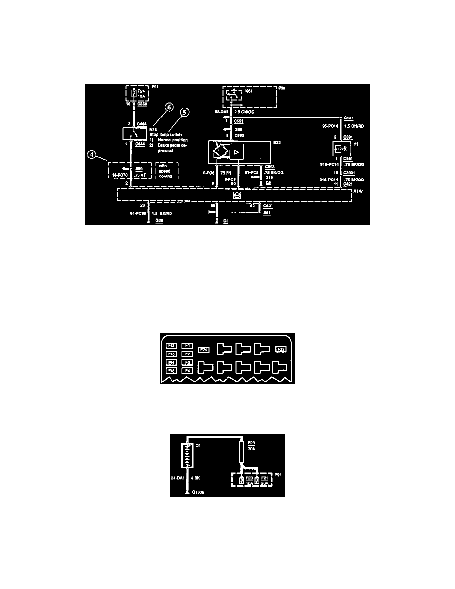
Within the diagram, all switches, sensors and relays are shown "at rest" (as if the Ignition Switch were OFF).
Splices (3)
An arrow indicates that the splice is not shown completely. If the splice is not shown completely in the diagram but is complete within the set of
diagrams, the number of the diagram where the splice is completed is indicated next to the arrow.
Boxes (4)
A thin dashed box on a diagram indicates a pan of the circuit which is only present for a particular vehicle model, country, or option. These qualifiers are
shown next to the box on the diagram.
Component Names and Notes (5)
Component names are placed on the right hand side of each component. Any notes that describe switch positions or operating conditions follow the
name. Descriptions of the internals of the component are also included here.
Component Identification Numbers (6)
Each component on each diagram has a component identification number located to the upper right hand side of the component. By finding this number
in the A-Z Component List, the Component Location description for that component can easily be found.
Fuse And Relay Information
Fuse and Relay Information
Fuse Box/Locations and Relay Box/Locations contain views of the fuse/relay box in which all fuses and relays are identified.
Power Distribution
Power Distribution
"Power Distribution" shows the current feed circuit. The Current path is shown from the battery to the ignition switch and to all fuses.