
Villager V6-201 3.3L SOHC VIN T SFI (1999)
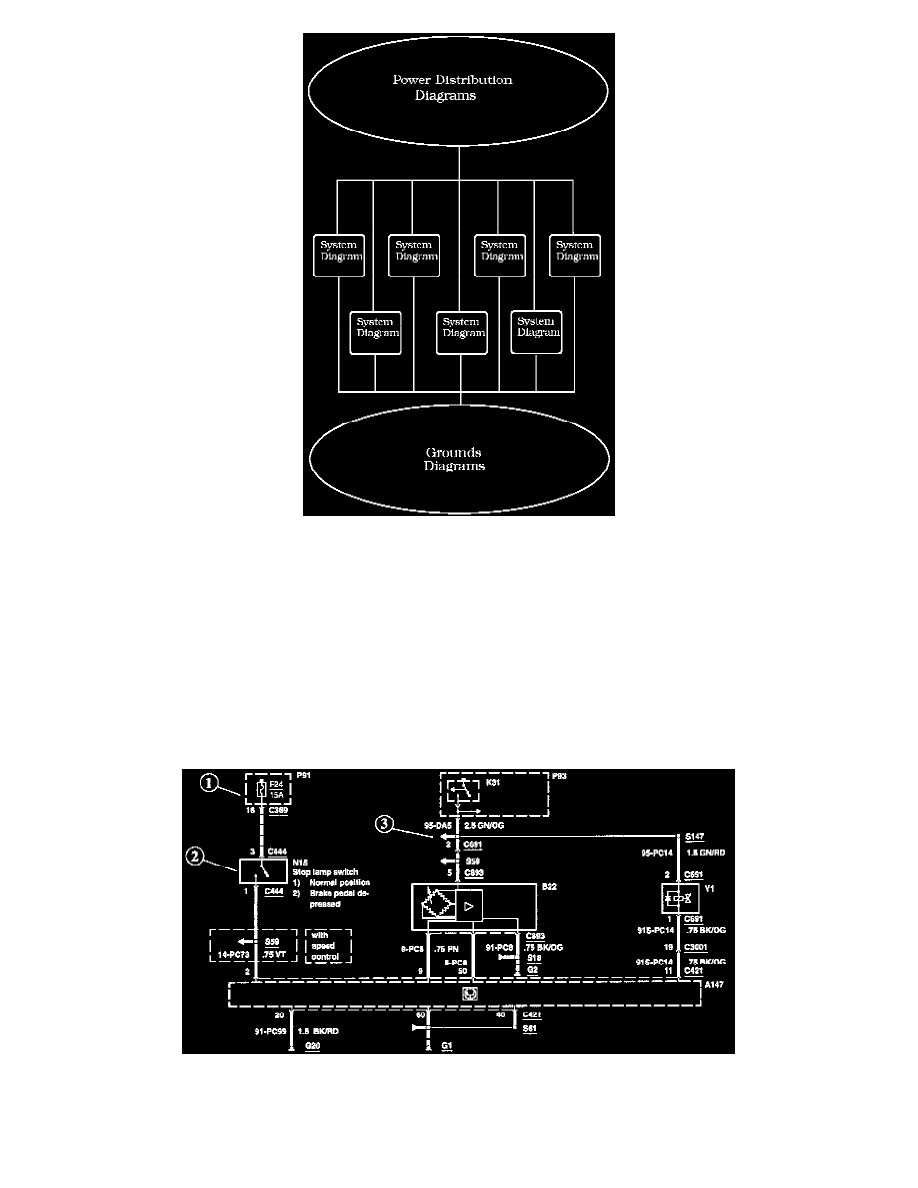
Diagrams are presented in three main categories:
-
Power Distribution Diagrams
-
System Diagrams
-
Grounds Diagrams
Note: All wiring connections between components are shown exactly as they exist in the vehicles. It is important to realize, however, that no attempt has
been made on the diagram to represent components and wiring as they physically appear on the vehicle. For example, a 4-foot length of wire is treated no
differently in a diagram from one which is only a few inches long. Furthermore, to aid in understanding electrical (electronic) operation, wiring inside
complicated components has been simplified.
Complete Circuit Operation
Each circuit is shown completely and independently in one set of diagrams. Other components which are connected to the circuit may not be shown
unless they influence the circuit operation.
Current Flow (1)
Each set of diagrams normally starts with the component that powers the circuit such as a fuse or the ignition switch. Current flow is shown from the
power source at the top of the diagram to ground at the bottom of the diagram. In order to concentrate on the essential parts, power supply and ground
connections are sometimes simplified by a dashed line in the diagrams.