
Villager V6-201 3.3L SOHC VIN T SFI (1999)
Fuse Circuits
Fuse Circuits
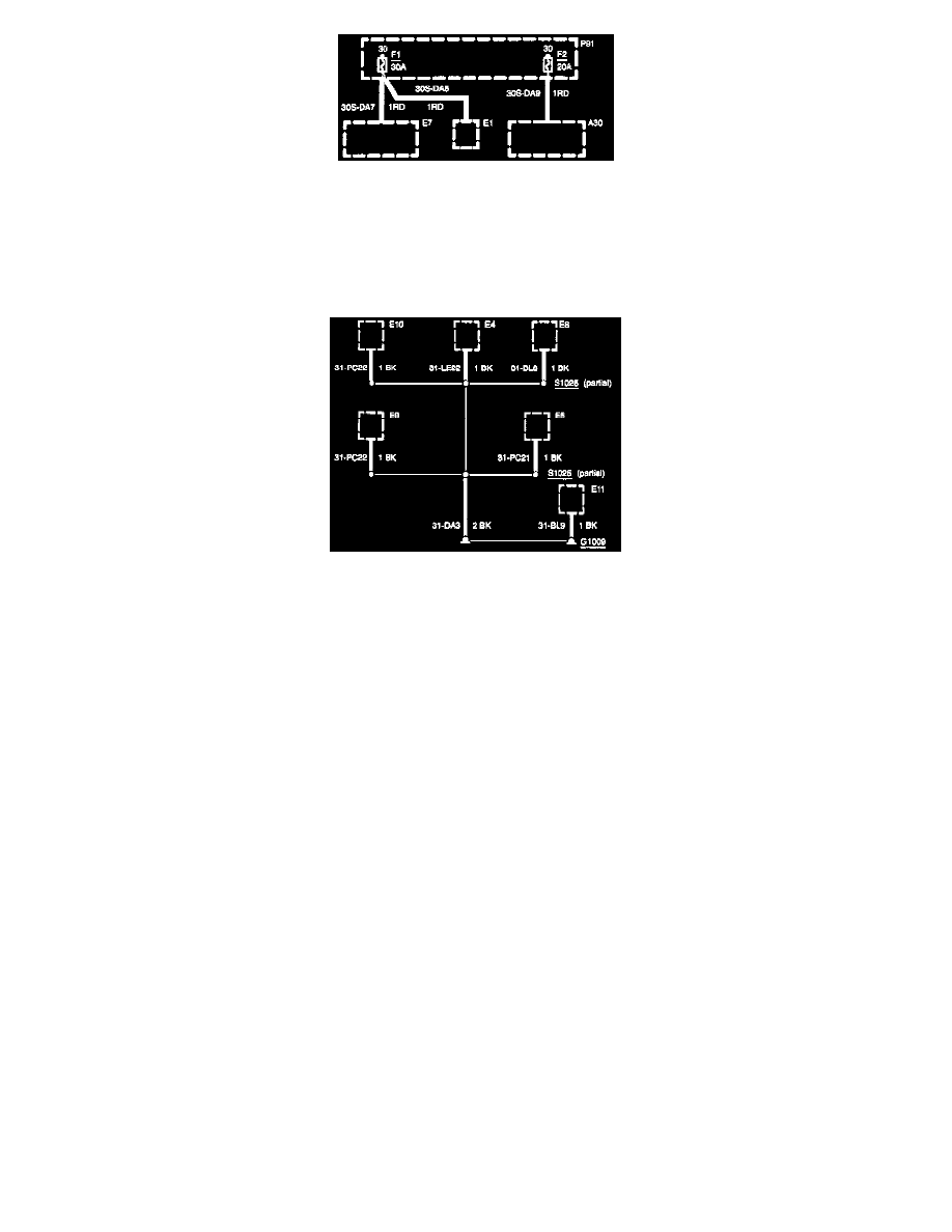
The first diagram in "Fuse Circuits" shows the circuits protected by each fuse. The circuit is traced from the fuse to the component. All details (wires,
splices, connectors) between the fuse and the first component are shown.
Any subsequent diagrams will show circuits feeding the fuse, all the way back to the battery.
Ground Distribution
Ground Distribution
"Ground Distribution" contains the diagrams that show the complete details for each ground connection or main ground splice. This is useful in
diagnosing a problem affecting several components at once (poor ground connection or ground splice). All details (wires, splices, connectors) between
the ground point and the components are shown. These ground connection details are shown here in order to keep the individual sets of diagrams as
uncluttered as possible.
Splices with a large number of wires may be split in order to improve the graphic representation. A thin line is used to indicate the unity of the splice.
The splice is then marked with the additional text "partial".
Component Identification Information
Component Identification Information consists of
(1) A-Z Component List,
(2) Component Location Views, and
(3) Connector views (Faces).
The A-Z Component List helps the user find where the various items depicted on the diagram can physically be found on the vehicle. A brief written
description of the location is given.
The Component Location Views show the components and their connecting wires as they can be found on the vehicle.
The Connector Views show the views of the pins and/or cavities of all connectors. The pin and cavity sides are shown separately as if the connector
were disconnected. The color of the connector housing is indicated next to the connector number.
Vacuum Motor Operation
Vacuum motors operate like electrical solenoids, mechanically pushing or pulling a shaft between two fixed positions. When vacuum is not applied, the
shaft is pushed all the way out by a spring.
Some vacuum motors can position the actuating arm at any position between fully extended and fully retracted. The Servo is operated by a control valve
that applies varying amounts of vacuum to the motor. The higher the vacuum level, the greater the retraction of the motor arm. Servo Motors work nearly
the same way as two-position motors, except for the way the vacuum is applied. Servo Motors are generally larger and provide a calibrated control.
A double diaphragm motor has three positions (it is actually two motors in one housing). When the top port gets vacuum, the shaft pulls halfway in.
When both ports get vacuum, the shaft pulls all the way in.