
Villager V6-201 3.3L SOHC VIN T SFI (1999)
Power Distribution Relay: Testing and Inspection
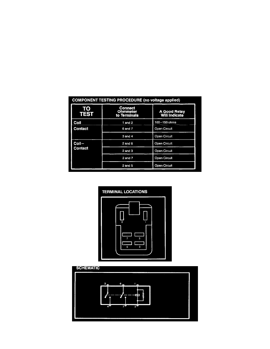
Component Testing Instructions
Component testing procedures are provided to determine whether a component is good or bad.
Testing information for each component includes a schematic with component terminal locations and step-by-step test procedures. Component
terminals are identified by letters or numbers that may be marked on the component or call out if there is no mark on the component.
The component connector MUST BE REMOVED before testing. To test a single circuit within the component, select that circuit under the column
TO TEST. If you wish to test the complete component, perform all tests.
COMPONENT TESTING PROCEDURE (Voltage Applied)
Disconnect the ohmmeter; connect pins 1, 6 and 3 to 12V DC power and pin 2 to ground. Measure voltage between pin 2 and pin 7. If the voltage is
12V, continue with the test. If not, replace the relay. Measure voltage between pins 2 and 5. If the voltage is 12V, the relay is okay. If not, replace the
relay.
Front Part 1