
Zephyr L6-200 3.3L (1982)
Valve Clearance: Adjustments
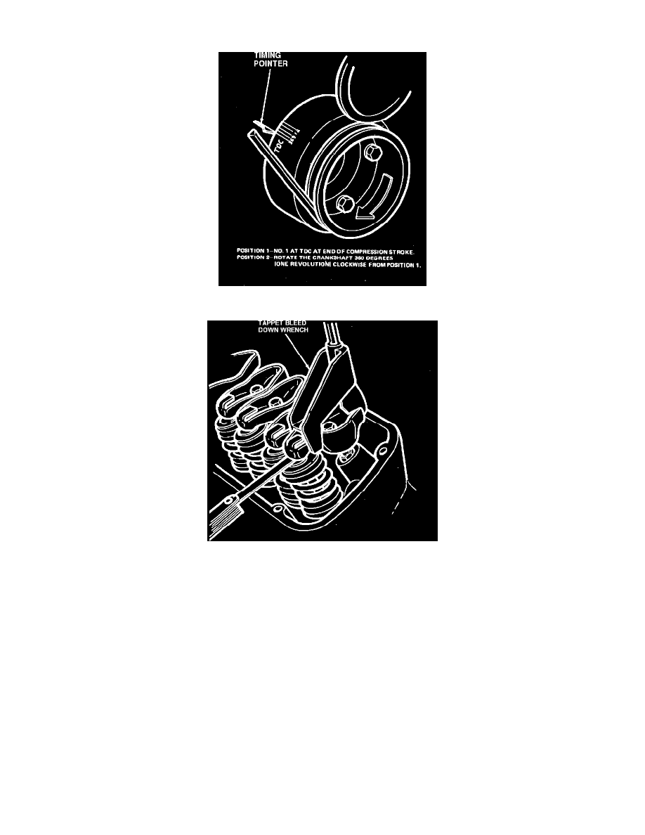
Fig. 4 Positioning crankshaft for valve clearance check
Fig. 5 Checking collapsed tappet clearance
Valve Arrangement
Front To Rear
6-200....................E-I-I-E-I-E-E-I-E-I-I-E
Valves, Adjust
A .060 inch longer or a .060 inch shorter push rod is available to compensate for dimensional changes in the valve train. If clearance is less than the
minimum, the .060 inch shorter push rod should be used. If clearance is more than the maximum, the .060 inch longer push rod should be used.
The procedure used to check the valve clearance is to rotate the crankshaft with an auxiliary starter switch until the No. 1 piston is near TDC at the end
of compression stroke, Fig. 4, and then compress the valve lifter with tool 6513-K or equivalent, Fig. 5. At this point the following valves can be
checked:
No. 1 Intake & No. 1 Exhaust.
No. 2 Intake & No. 3 Exhaust.
No. 4 Intake & No. 5 Exhaust.
After these valves have been checked, rotate crankshaft until No. 6 piston is on TDC at the end of its compression stroke (1 revolution of the crankshaft),
Fig. 4, and then compression valve lifter with tool 6513-K or equivalent. Check the following valves.
No. 3 Intake & No. 2 Exhaust.