
3000GT AWD V6-2972cc 3.0L DOHC Turbo (1991)
Alignment: Service and Repair
Preliminary Check
1.
Ensure tires are inflated to correct pressure, then check for uneven wear.
2.
Check front wheel bearings, suspension arm, and ball joints for damage and replace components as necessary, to eliminate improper alignment due
to faulty components.
3.
Check steering gear for damage and adjust as necessary.
4.
Check shocks for damage and replace as necessary.
5.
Rock vehicle backward and forward and bounce it upward and downward to settle vehicle prior to alignment.
6.
Ensure vehicle is unloaded and on a suitable alignment rack according manufacturers' instructions. When measuring equipment is attached
directly to outer end of driveshaft and front wheels are on turntables, apply brake to prevent improper vehicle movement.
Front Camber
1.
Install wheel alignment gauge attachment tool No. MB991004 or equivalent. Tighten to same torque as front driveshaft nut.
2.
To adjust, turn strut tower lower mounting bolt (upper). One graduation is equivalent to about 1/3° in camber.
Rear Camber
AWD Models
1.
Measure camber with a camber/caster/kingpin gauge.
2.
Adjust camber by moving mounting bolt located on crossmember side of lower arm. One graduation is equivalent to about 1/5° in camber.
FWD Models
1.
Make adjustment with crossmember side assist link mounting bolt loosened.
2.
Adjust camber by turning lower arm mounting bolt (crossmember side). One graduation is equivalent to about 1/4° in camber.
3.
If camber is adjusted ensure to adjust toe-in.
Front Caster
Caster has been preset during production and is not adjustable.
Rear Toe-In
AWD
1.
Adjust rear toe-in by moving mounting bolts located on crossmember side of the trailing arm.
2.
Make adjustment by moving left and right bolts equally. One graduation changes toe by approximately .08 inch.
FWD
Adjust rear toe-in by turning the crossmember side assist link mounting bolts on both sides the same amount. One graduation changes toe by
approximately .19 inch.
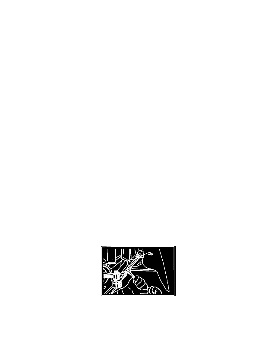
Front Toe-In
Fig. 1 Front Toe-In Adjustment
1.
Adjust toe-in by loosening clips and turning left and right tie rod turnbuckles equally in opposite directions. Refer to Fig. 1.
2.
To increase toe-out, turn left turnbuckle toward front of vehicle and right turnbuckle toward rear of vehicle. To increase toe-in, turn turnbuckles in
other direction.
3.
Amount of toe-in adjustment is as follows:
a. .24 inch for each half turn of left and right tie rods.