
3000GT AWD V6-2972cc 3.0L DOHC Turbo (1991)
Crankshaft Position Sensor: Description and Operation
Crankshaft Position Sensor (CKP)
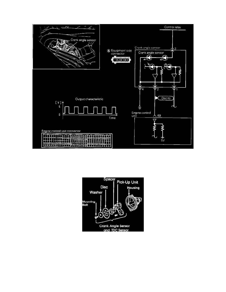
Crank Angle Sensor Circuit
The Crank Angle Sensor and the Top Dead Center Sensor are located on the rear of the back cylinder head. These sensors are incorporated into one unit,
being a disc and a pick-up unit. The disc is affixed to a shaft that is coupled to the camshaft and the light-transmitting unit is mounted stationary to the
units housing.
Crank Angle And #1 TDC Sensor
The disc contains slits around its circumference with a blank space to indicate the crankshaft angle. An additional six light-transmission slits located 60°
apart located inward from the edge are used to indicate number one cylinder's top dead center position. The pick-up unit assembly uses two luminous
diodes and two photo diodes, in order to be able to detect the two different slits. There is a very slight clearance between the luminous diodes and the
photo diodes, and the disc rotates within this space. As the shaft rotates, the slits at the discs edge pass between the light and the optical receptor part of
the unit. The light emitted from the luminous diodes pass through the slits to the photo sensing diodes. When the photo diodes receive the light, they
become conductive and generate a signal, which is sent to the Control Unit.
The Control Unit is able to detect number one cylinder TDC by comparing the signal generated through the inner slits on the disc and the blank space in
the outer slits.
The slits at the outer circumference of the disc serve to detect the position of the crankshaft (and, therefore, the piston) relative to top dead center.