
3000GT AWD V6-2972cc 3.0L DOHC Turbo (1991)
Electric Load Sensor: Testing and Inspection
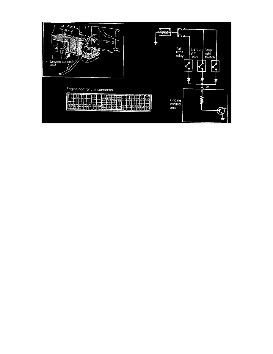
Electric Load Switch Circuit
To test the electrical load switch located in the ECU, three separate switch circuits need to be checked. This verifies all inputs are working correctly.
1. Disconnect the ECU harness connector.
2. Turn "ON" the lighting switch. This activates the tail lamp relay.
3. Measure the input voltage between the ECU harness connector terminal 24 and ground.
Voltage
System Voltage
4. Turn "ON" the defogger switch, this activates the defogger relay.
5. Measure the input voltage between the ECU harness connector terminal 24 and ground.
Voltage
System Voltage
6. Depress the brake pedal, this activates the stop lamp switch.
7. Measure the input voltage between the ECU harness connector terminal 24 and ground.
Voltage
System Voltage
If any of the previous tests produce unsatisfactory results, the harness will need to be repaired or replaced, of switches adjusted. Once repairs have
been completed, road test the vehicle to confirm that the repair has corrected the problem.
If the same problem reoccurs, it is possible that there is an intermittent failure of the component or the ECU. Check for looseness at all harness
junctions and test for an intermittent failure.