
3000GT Convertible AWD V6-2972cc 3.0L DOHC Turbo (1995)
Engine Control Module: Pinout Values and Diagnostic Parameters
California
1
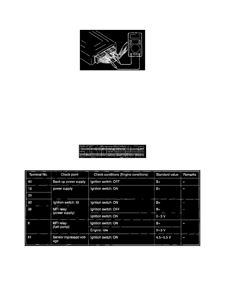
Connect a very thin wire probe (such as a paper clip) to the probe of the voltmeter.
2
Insert the very thin probe from the wire side into contact with each of the terminals of the ECM connector and check the voltage, while referring to
the check chart.
NOTE
1. Measure a voltage with the ECM connector connected.
2. Measure the voltage between each terminal and the No. 26 terminal (ground terminal).
3. Withdraw the ECM for easier access to the connector terminals.
4. The inspection need not be performed in the order of the chart.
Caution: Short-circuiting the positive (+) probe between a connector terminal and ground could cause damage to the vehicle wiring, sensors or
ECM, or all of them. Use care to prevent it!
3
If the voltmeter shows any deviation from the standard value, check the corresponding sensor, actuator and related electrical wiring, then repair or
replace.
4
After repair or replacement, recheck with the voltmeter to confirm that the problem has cleared completely.
Engine Control Module Connector Terminal Configuration