
3000GT SL V6-2972cc 3.0L DOHC MFI (1997)
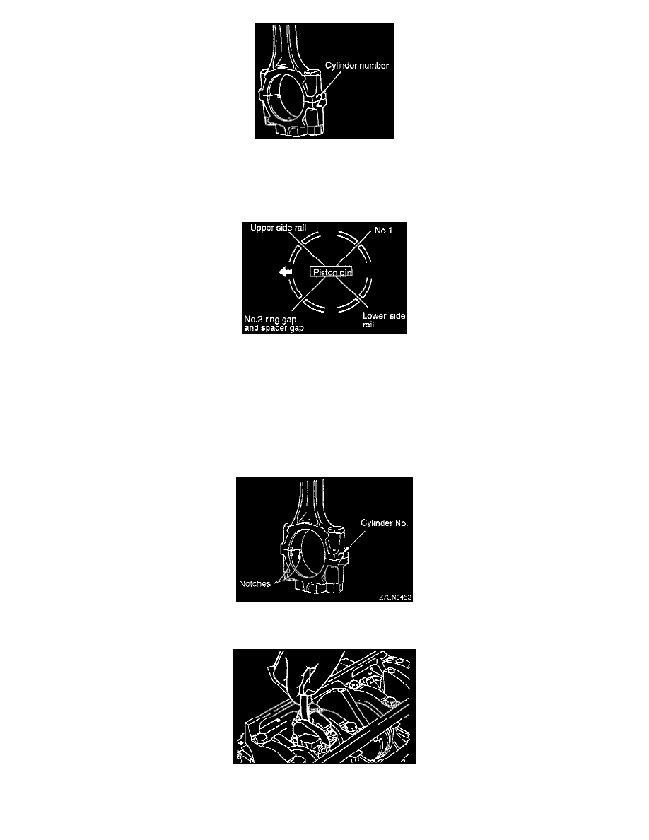
1. Mark the cylinder number on the side of the connecting rod big end for correct reassembly.
2. Keep the removed connecting rods, caps, and bearings in order according to the cylinder number.
3. Service the piston pin.
4. Service the piston rings.
5. Liberally coat engine oil on the circumference of the piston, piston ring, and oil ring.
6. Arrange the piston ring and oil ring gaps (side rail and spacer) as shown in the figure.
7. Rotate crankshaft so that the crank pin is on center of cylinder bore.
8. Use suitable thread protectors on the connecting rod bolts before inserting piston and connecting rod assembly into the cylinder block. Care must
be taken not to nick the crank pin.
9. Using a suitable piston ring compressor tool, install the piston and connecting rod assembly into the cylinder block.
NOTE:
-
Install the piston with the front mark (arrow mark) on the top of the piston directed towards the engine front (timing belt side).
-
Two types of pistons have been used, one for cylinders 1, 3 and 5 and the other for cylinders 2, 4 and 6. Piston with "R" are for cylinders 1, 3
and 5 and piston with an "L" are for cylinders 2, 4 and 6.
10. Mate the correct bearing cap with the correct connecting rod by checking with the alignment marks marked during disassembly. If a new
connecting rod is used which has no alignment mark, position the notches for locking the bearing on the same side.
11. Tighten the rod nuts to 52 Nm (38 ft. lbs.) and check if the thrust clearance in the connecting rod big end is correct.
Standard value: 0.10-0.25 mm (0.0039-0.0098 inch)
Limit: 0.4 mm (0.016 inch)