
3000GT SL V6-2972cc 3.0L DOHC MFI (1997)
INSPECTION USING SCAN TOOL
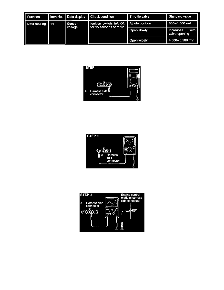
HARNESS INSPECTION
STEP 1: Measure the power supply voltage of the throttle position sensor.
-
Connector: Disconnected
Ignition switch: ON
Voltage: 4.8-5.2 V
OK: GO TO STEP 2
NG: Repair the harness. (Al -81)
STEP 2: Check for continuity of the ground circuit.
-
Connector: Disconnected
OK: GO TO STEP 3
NG: Repair the harness. (A4-92)
STEP 3: Check for an open-circuit, or a short-circuit to ground between the engine control module and the throttle position sensor.
-
Throttle position sensor connector: Disconnected
-
Engine control module connector: Disconnected
-
Connector of any control module which uses TPS output signals like ECM: Disconnected
OK: STOP
NG: Repair the harness. (A2-84)
THROTTLE POSITION SENSOR CHECK