
3000GT SL V6-2972cc 3.0L DOHC MFI (1997)
Variable Induction Position Sensor: Testing and Inspection
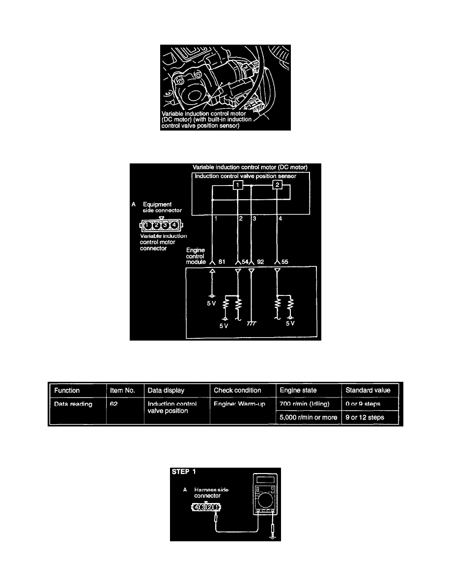
OPERATION
-
The induction control valve position sensor detects the induction control valve opening degree and converts it into a pulse signal to be input into
the engine control module, which provides valve opening and closing control based on this signal.
-
The induction control valve position sensor is supplied with 5V power engine control module and is grounded to the engine control module. A
voltage of 5V from the engine control module is impressed to the two output terminals of the induction control valve position sensor. By opening
and closing the circuit between the output terminal and ground, the induction control valve position sensor generates the pulse signal.
INSPECTION USING SCAN TOOL
HARNESS INSPECTION
STEP 1: Measure the power supply voltage of the air intake control valve position sensor.