
3000GT VR-4 AWD V6-2972cc 3.0L DOHC MFI Twin Turbo (1998)
(2) Check that there is continuity [11 - 18 Ohms at 20°C (68°F)] across terminals (1) and (3) of the heated oxygen sensor connector.
(3) If there is no continuity, replace the heated oxygen sensor.
(4) Warm up the engine until the engine coolant temperature becomes 80°C (176°F) or higher.
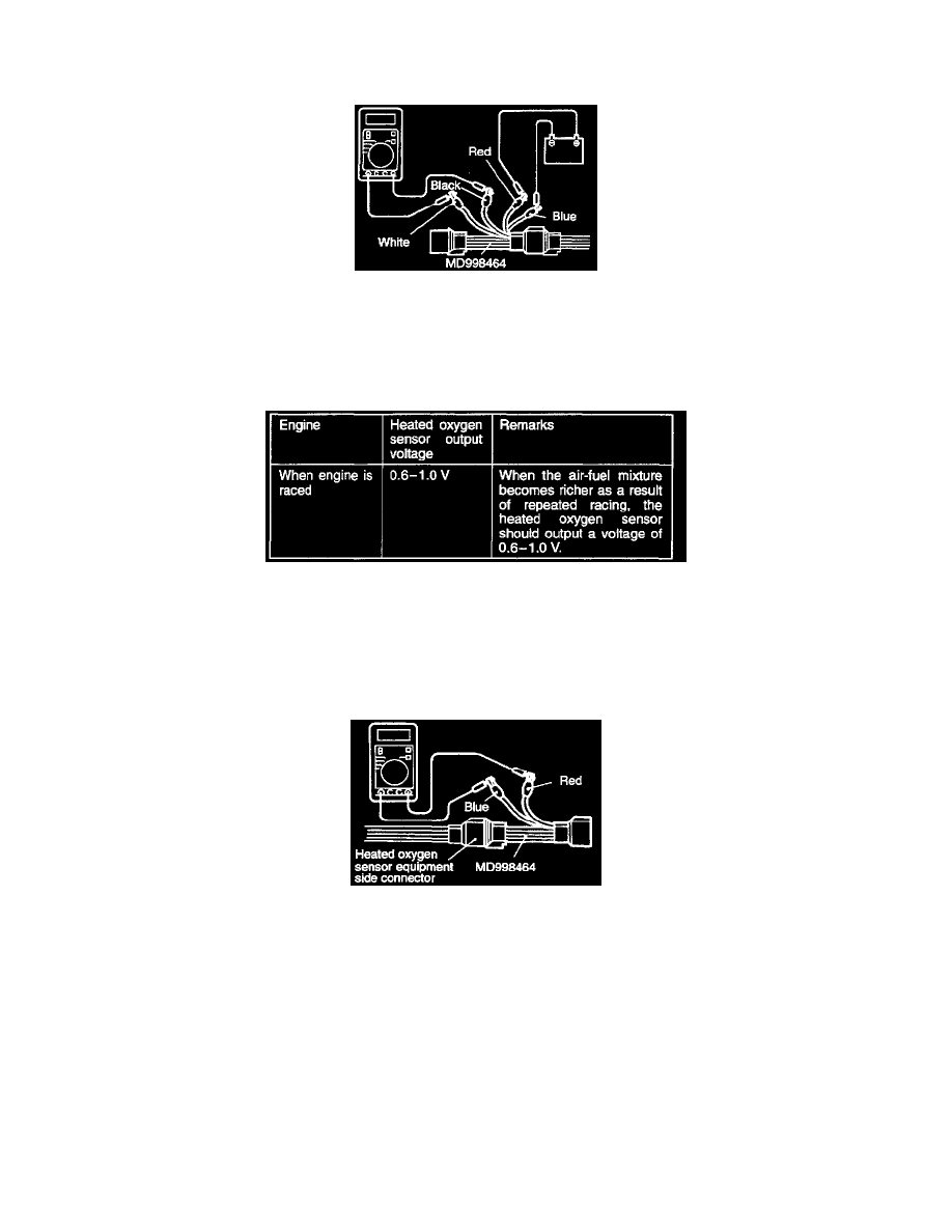
(5) Using jumper wires, connect terminals (1) (red clip of the special tool) and (3) (blue clip) of the heated oxygen sensor connector to battery (+) arid
(-) terminals respectively.
CAUTION: Ensure that the jumper wires are connected correctly, as wrong connections result in a broken heated oxygen sensor.
(6) Connect a digital voltmeter across terminals (2) (black clip of the special tool) and (4) (white clip).
(7) Race the engine repeatedly and measure the output voltage of the heated oxygen sensor.
(8) If the measurements are not as specified, defective heated oxygen sensor is suspected.
NOTE: For removal and installation of the heated oxygen sensor (front) refer to GROUP 15 - Exhaust Pipe Main Muffler and Catalytic
Converter.
<Heated Oxygen Sensor (rear)>
(1) Disconnect the heated oxygen sensor (rear) connector and connect the special tool (test harness) to the connector on the heated oxygen sensor
(rear) side.
(2) Make sure that there is continuity [11 - 18 Ohms at 20°C (68°F)] between terminals No.2 (red clip of the special tool) and terminal No. 4 (blue
clip) on the heated oxygen sensor (rear) connector.
(3) If there is no continuity replace the heated oxygen sensor (rear).
NOTE:
If the scan tool does not display the standard value although no abnormality is found by the above mentioned continuity test and harness check,
replace the heated oxygen sensor (rear)..