
Cordia L4-2.0L SOHC (1984)
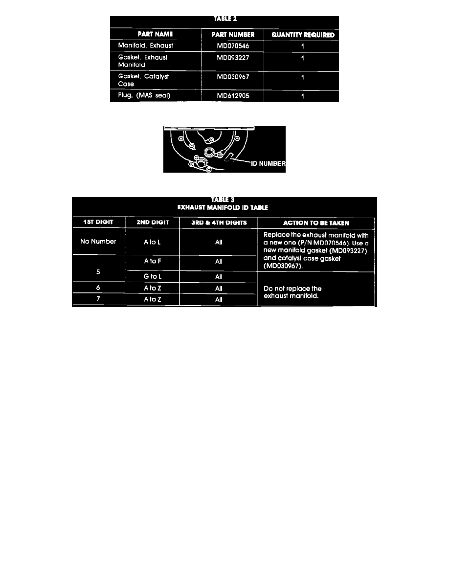
Parts for the conditional operations are listed in Table 2 below.
FIGURE 1
REPAIR PROCEDURE
1.
This procedure should be peformed on a cold engine.
2.
Remove the exhaust manifold heat protector. Check the ID number which is cast into the top of the exhaust manifold (Figure 1). Take action as
shown in Table 3 below. If manifold is cracked, replace it.
3.
Remove the carburetor as follows.
A.
Install locking clamp pliers on the coolant hose from the intake manifold to the choke thermo wax housing to prevent excessive coolant
leakage. Then twist and disconnect the hose from the carburetor.
B.
Disconnect the accelerator cable and wire harness connector from the carburetor, then remove the fuel lines and hose connections.
C.
Remove the four carburetor through bolts and washers, and the nut and lock washer at the left rear corner of the carburetor near the sub-EGR
valve.
D.
Lift the carburetor off the intake manifold.
NOTE:
Usually a quick, hard pull will separate the carburetor from the intake manifold. Cover the exposed intake manifold ports with a shop
towel.
E.
Support the carburetor. Take caution not to damage the throttle linkage that extends below the base of the carburetor.
4.
Install a choke shim to the choke adjust screw as described below.
A.
Using the fast idle release driver special tool included with this bulletin, spread the choke linkages to create a gap between the choke adjust
screw and the plunger of the thermo wax element.
B.
With the linkages spread, use needle nose pliers to install the choke shim (cap) from the service kit onto the threaded end of the choke adjust