
Diamante Sedan V6-3.5L SOHC (1999)
Engine Control Module: Pinout Values and Diagnostic Parameters
Terminal Resistance and Continuity Check
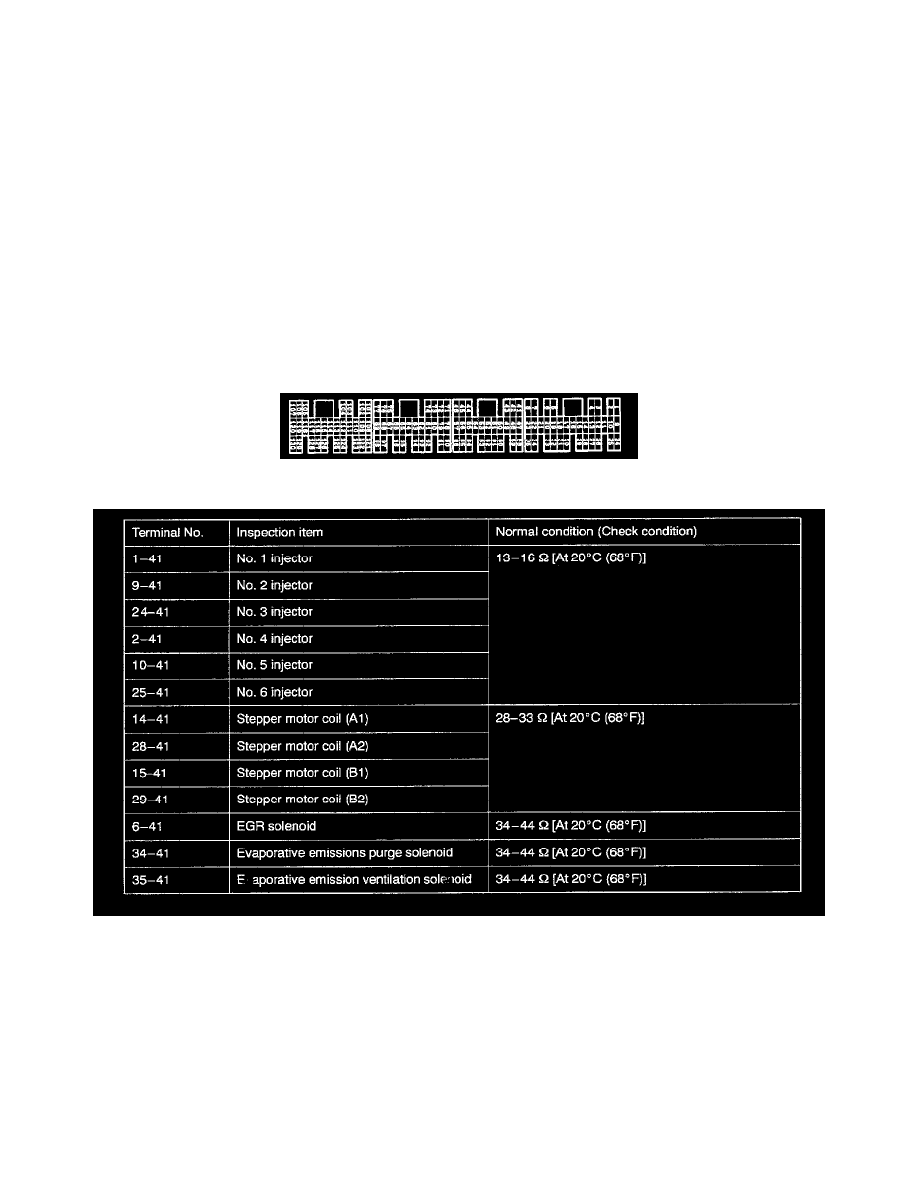
TERMINAL RESISTANCE AND CONTINUITY CHECK
1. Turn the ignition switch to OFF.
2. Disconnect the ECM connector.
3. Measure the resistance and check for continuity between the terminals of the ECM harness-side connector while referring to the check chant.
NOTE: When measuring resistance and checking continuity, a harness for checking contact pin pressure should be used instead of inserting a test
probe.
NOTE: Checks do not have to be carried out in the order given in this chart
CAUTION: If resistance or continuity checks are performed on the wrong terminals, damage to the vehicle wiring, sensors, ECM, and/or
ohmmeter may occur. Use care to prevent this!
4. If the ohmmeter shows any deviation from the normal condition, check the corresponding sensor, actuator and related electrical wiring, and then
repair or replace.
5. After repair or replacement, recheck with the ohmmeter to confirm that the repair or replacement has corrected the problem.
Connector View
Resistance Values Part 1 Of 2