
Eclipse L4-1795cc 1.8L SOHC (1990)
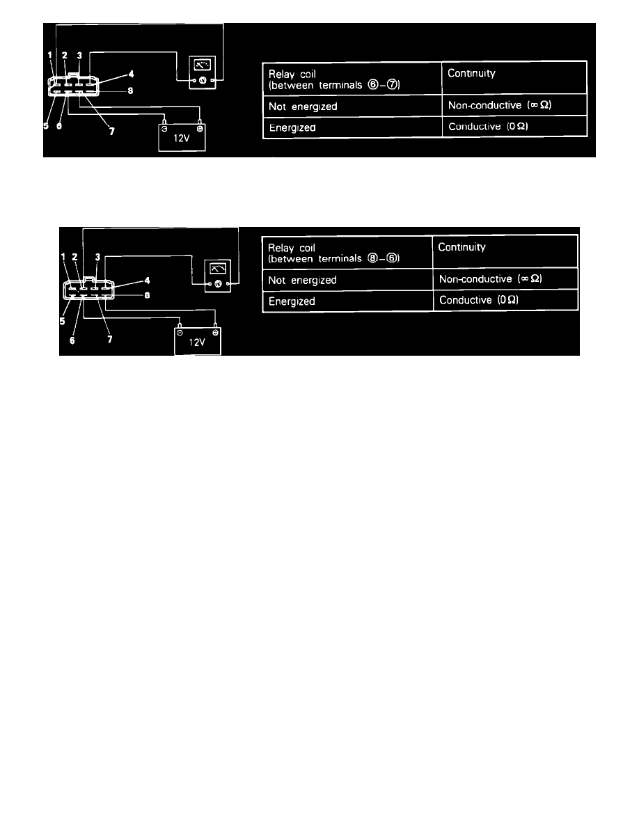
Fig. 2 Control Relay Test
3. Using an ohm meter, check the resistance terminals 1 and 4, when Voltage is supplied and not supplied between terminals 6 and 7 as shown in FIG.
2.
Fig. 3 Control Relay Test
4. Using an ohm meter, check the resistance terminals 2 and 4, when Voltage is supplied and not supplied between terminals 6 and 8 as shown in FIG.
3.
HARNESS TEST
1. Disconnect the control relay and turn the key to the ON position.
2. Using a volt meter, check the Voltage between relay harness terminal 8 and ground.
Voltage
System Voltage.
3. Turn the key to the OFF position.
4. Using an ohm meter, check for continuity between relay harness terminal 6 and ground.
Continuity
Should exist.
5. Using a volt meter, check the Voltage between relay harness terminal 4 and ground.
Voltage
System Voltage.
6. Disconnect the negative battery cable and the ECU connector.
7. Using an ohm meter check for continuity between relay harness connector 3 and ECU harness connectors 107 and 102.
Continuity
Should exist.
8. Using an ohm meter check for continuity between relay harness connector 3 and ground.
Continuity
Should not exist.
If any of the previous tests produce unsatisfactory results, the harness will need to be repaired or replaced. Once repairs have been completed, road
test the vehicle to confirm that the repair has corrected the problem.