
Eclipse L4-1996cc 2.0L DOHC (1995)
11.
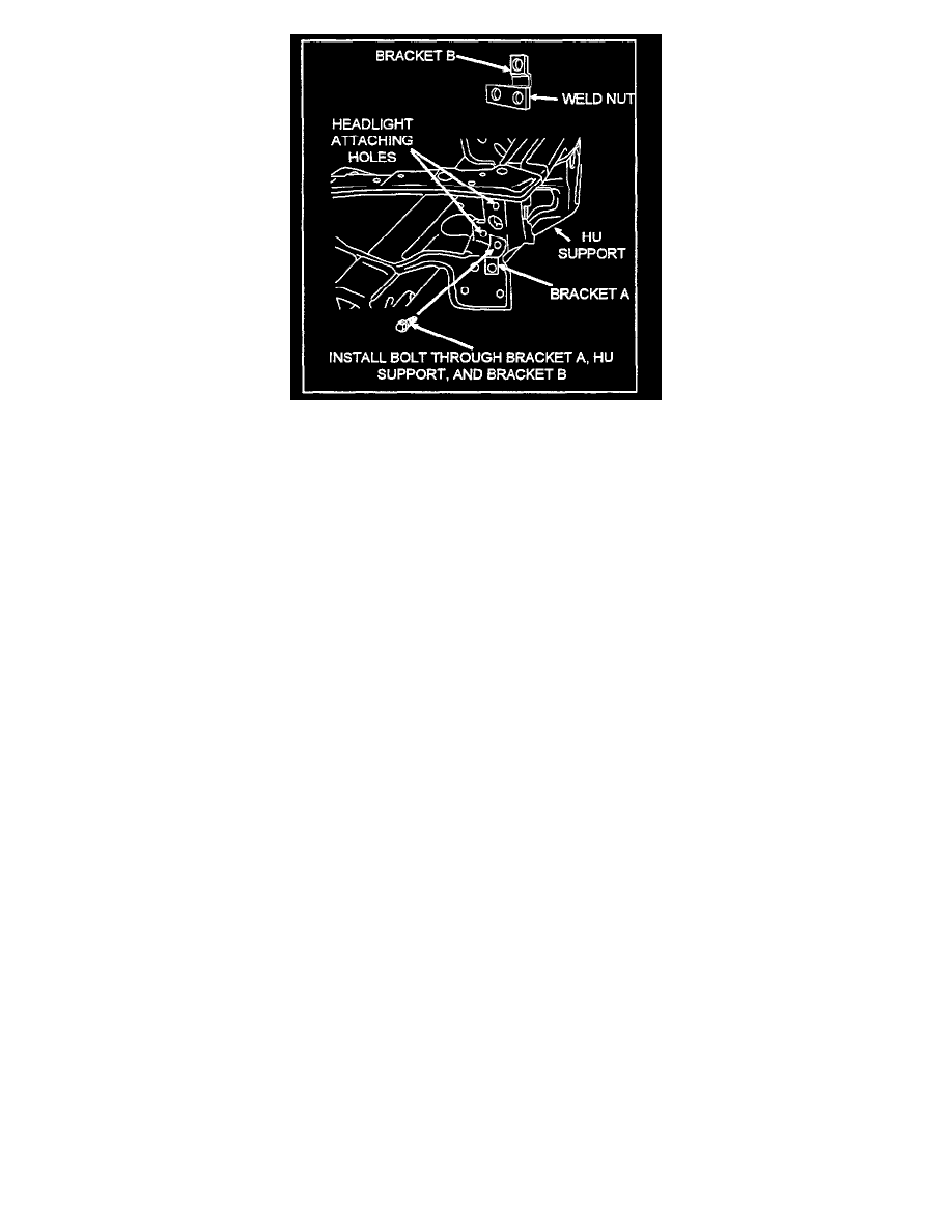
Hold bracket B behind the HU support (on the HU-side) and align its weld-nut with the 5/16" hole. Install the bolt removed in Step B through the
upper hole of bracket A, the 5116" hole, and the weld-nut of bracket B. Before tightening the bolt, make sure the two other holes on bracket B are
aligned with the two existing headlight attaching holes on the HU support. Tighten the bolt 14 Nm (10 ft. lbs.).
12.
Attach the turn signal wiring harness to the headlight assembly. Reinstall the headlight assembly, making sure the tab on the lower edge does not
damage the fascia. From under the vehicle, attach the main headlight wiring harness.
13.
Reinsert the trim stick between the fascia and lower edge of the headlight (as previously done in Step 3).
If a magnetic socket is not available, place a small piece of tape on the bolt head of the lower headlight mounting bolt and insert the bolt into a 10
mm swivel socket. (This will allow the bolt to remain in the socket until it is attached.)
Using a drive extension, install the bolt in the lower headlight mounting hole. Tighten the bolt 5 Nm (44 in. lbs.). Remove the trim stick.
NOTE:
Step 13 is difficult to perform and requires good manual dexterity. To ensure safe headlight operation, the lower headlight mounting bolt
MUST be installed.
14.
Align the top headlight tab with the mark made in Step 4. Install the top and rear headlight bolts, tightening each bolt 5 Nm (44 in. lbs.).
15.
Remove the masking tape from the fascia, and check for normal aim/operation of the headlight.