
Eclipse L4-1997cc 2.0L DOHC (1991)
2. REMOVAL OF CONNECTING ROD CAP
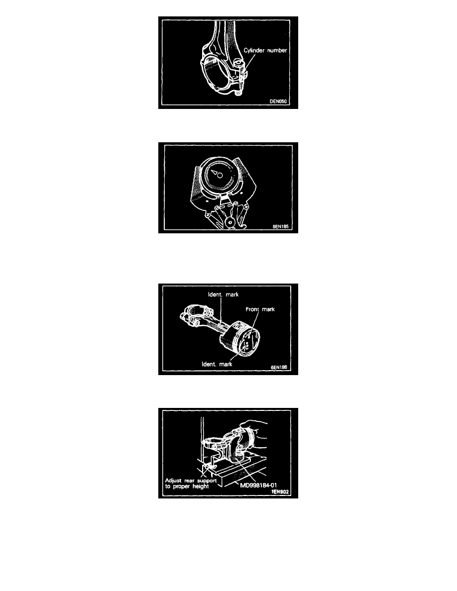
Mark the large end of the. connecting rod with the cylinder number for use during reassembly.
7. REMOVAL OF NO.1 PISTON RING/8. NO.2 PISTON RING
Remove the piston rings with a piston expander.
10. REMOVAL OF PISTON PIN
1. Fit the piston and the connecting rod assembly to the body of the special tool. Set the front mark (Triangle) on the upper surface of the piston
and the front mark (G6) in the center of the connecting rod so that they face upwards.
2. Place piston and connecting rod with arrow mark or identification mark upward over anvil so lip of insert in between connecting rod boss and
inside surface of piston. The connecting rod boss should bear on as much of the insert surface as possible.
3. Adjust connecting rod rear support until rod is horizontal to press bed surface. Misalignment of pin and receiving tube may result if support
adjustment is not correct.