
Eclipse L4-1997cc 2.0L DOHC (1991)
Main Relay (Computer/Fuel System): Testing and Inspection
Non Trouble Code Components
Control Relay
Failure of the control relay could interrupt power supply to the fuel pump, injectors and ECU, resulting in start failure.
CAUTION: Use caution when connecting jumper wires to the relay. If the polarity is incorrectly connected, the relay will be damaged.
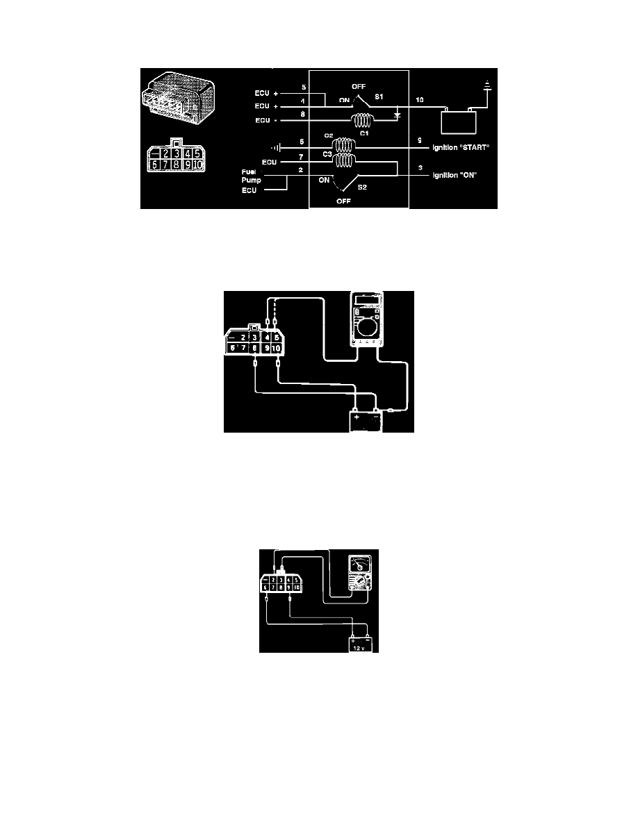
Fig. 1 Relay Test
COMPONENT TEST
1. Supply 12 VDC to relay terminals 8 (-) and 10 (+). Using a Voltmeter, check for Voltage between terminals 4 (+) and 8 (-) and between terminals 5
(+) and 8 (-). Refer to Fig. 1.
Voltage
12 VDC
Fig. 2 Relay Test
2. Supply 12 VDC to relay terminals 6 (-) and 9 (+). Using an ohmmeter, check for continuity between terminals 2 and 3. Refer to Fig. 2.
Continuity
Should exist when Voltage is supplied.
Should NOT exist when Voltage is NOT supplied.