
Eclipse L4-1997cc 2.0L DOHC (1991)
Main Relay (Computer/Fuel System): Testing and Inspection
Power and Ground Supply Circuits
CONTROL RELAY
Failure of the control relay could interrupt power supply to the fuel pump, injectors and ECU, resulting in start failure.
Caution Use caution when connecting jumper wires to the relay. If the polarity is incorrectly connected, the relay will be damaged.
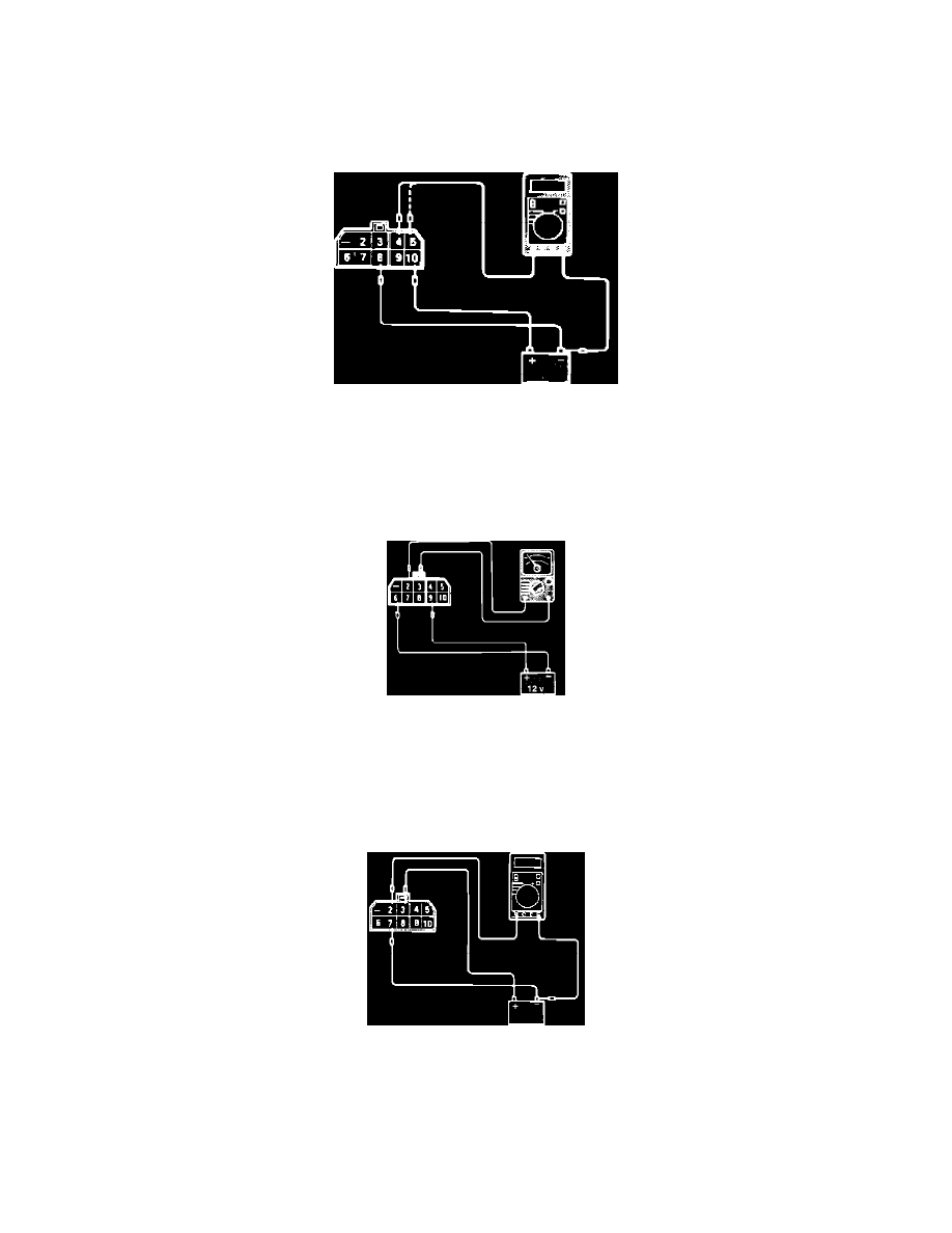
Fig. 1 Relay Test
1. Supply 12 VDC to relay terminals 8 (-) and 10 (+). Using a Voltmeter, check for Voltage between terminals 4 (+) and 8 (-) and between terminals 5
(+) and 8 (-). Refer to Fig. 1.
Voltage
12 VDC
Fig. 2 Relay Test
2. Supply 12 VDC to relay terminals 6 (-) and 9 (+). Using an ohmmeter, check for continuity between terminals 2 and 3. Refer to Fig. 2.
Continuity
Should exist when Voltage is supplied.
Should NOT exist when Voltage is NOT supplied.
Fig. 3 Relay Test
3. Supply 12 VDC to relay terminals 7 (-) and 3 (+). Using a Voltmeter, check for Voltage between terminals 2 (+) and supply battery ground
terminal. Refer to Fig. 3.
Voltage
12 VDC when terminal 7 is connected.
0 VDC when terminal 7 is NOT connected.