
Eclipse L4-1997cc 2.0L DOHC (1991)
-
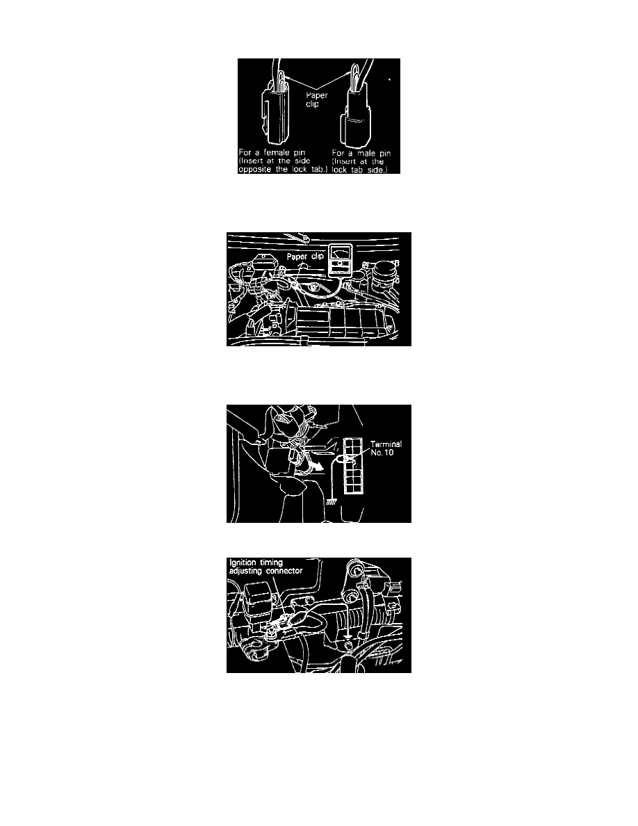
Insert a paper clip (from the harness side) into the 1-pin connector shown in the figure.
Tachometer Connector Usage
Caution: The paper clip should be inserted between the terminals as shown in the figure above.
-
Connect a primary-Voltage-detection type of tachometer to the paper clip.
NOTE: For rpm, one-half of the actual engine rpm is indicated, so the actual engine rpm is two times the indicated value shown by the tachometer.
-
Use a jumper wire to ground the diagnostic test mode control terminal of the data link connector.
4. Use a jumper wire to ground the terminal for adjustment of ignition timing.
5. Start the engine and let it idle.
6. Check the standard idling rpm.
If the scan tool is used, select item No.22 and read out the idling rpm.
Basic idle speed: 750 ± 50 rpm
NOTE:
-
The engine speed may be 20 to 100 rpm lower than indicated above for a new vehicle (driven approximately 500 km: (300 miles) or less], but